Rainbow Electronics MAX6871 User Manual
Page 46
MAX6870/MAX6871
Forcing Programmable
Outputs High During Power-Up
A weak 10µA pulldown holds all programmable outputs
low during power-up until ABP exceeds the undervolt-
age lockout (UVLO) threshold. Applications requiring a
guaranteed high programmable output for ABP down to
GND require external pullup resistors to maintain the
logic state until ABP exceeds UVLO. Use 20k
Ω resis-
tors for most applications.
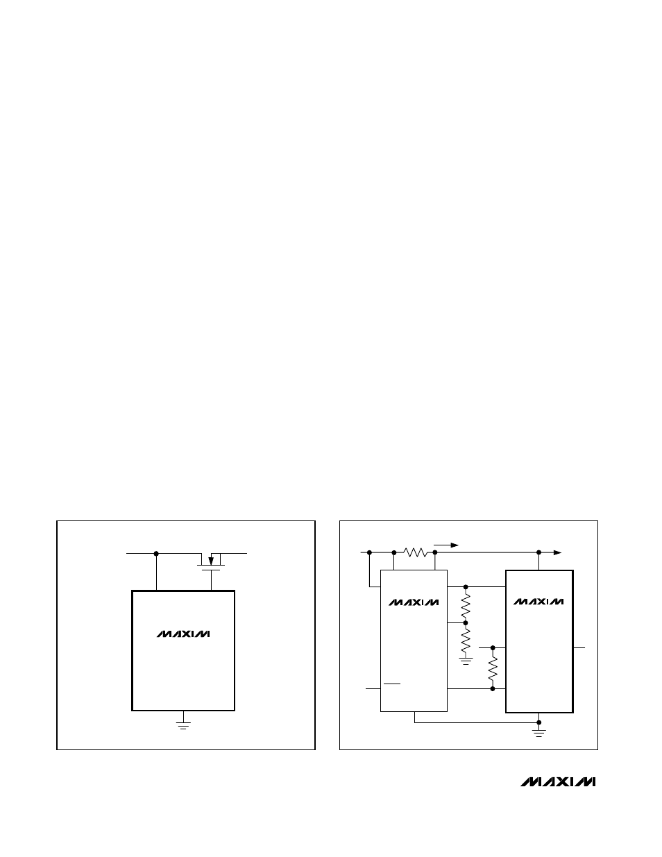
Driving High-Side MOSFET
Switches with the MAX6870/MAX6871
High-side MOSFET switches are commonly used in
power-supply sequencing applications. First, configure
the programmable output of the MAX6870/MAX6871 as
an active-low charge-pump output and set the condi-
tions to assert this output. Connect the programmable
output to the gate of an n-channel MOSFET. As the
conditions to deassert this output are met, the output
deasserts high (V
ABP
+5V), turning on the FET, thus
allowing the voltage on the drain to pass through to the
downstream device (see Figure 9).
Uses for General-
Purpose Inputs (GPI1–GPI4)
Watchdog Timer
Program GPI_ as an input to one of the watchdog
timers in the MAX6870/MAX6871. The GPI_ input must
toggle within the watchdog timeout period, otherwise
any programmable output dependent on the watchdog
timer asserts.
Additional Manual Reset Functions
The PO7 (MAX6870)/PO5 (MAX6871) programmable
outputs allow a single set (Product 1 only) of conditions
to assert the output. Program the set of conditions to
depend on one of the GPI_ inputs. Any output that
depends on GPI_ asserts when GPI_ is held in its
active state, effectively acting as a manual reset input.
Other Fault Signals from µC
Connect a general purpose output from a µC to one of
the GPI_ inputs to allow interrupts to assert any output
of the MAX6870/MAX6871. Configure one of the pro-
grammable outputs to assert on whichever GPI_ input
connects to the general purpose output of the µC.
Uses for AUXIN1 and AUXIN2
Analog Output of Current-Sense Amplifier
Figure 10 shows the MAX6870/MAX6871 in a current-
sensing application with the MAX4374. The MAX4374
generates an analog output voltage (OUT) proportional
to the voltage difference between RS+ and RS- and a
latched comparator output (COUT) indicating an over-
current condition. Connect OUT to AUXIN1 to provide
continuous monitoring of the load current on the 12V
supply. The internal ADC of the MAX6870/MAX6871
digitizes V
OUT
and stores the results in read-only regis-
ters 5Ch through 5Fh. COUT latches high for V
CIN
>
600mV, and clears with the RESET input of the MAX4374.
Configure GPI1 as an active-high input and configure
PO7 (MAX6870)/PO5 (MAX6871) to depend on GPI1.
PO7/PO5 asserts to its active state when an overcurrent
condition exists.
EEPROM-Programmable Hex/Quad
Power-Supply Sequencers/Supervisors with ADC
46
______________________________________________________________________________________
IN3
PO1
TO
LOAD
+5V
GND
MAX6870
MAX6871
Figure 9. Driving High-Side n-Channel MOSFET Switches
IN1
RS-
RS+
+12V
R
SENSE
R1
R2
R3
+5V
I
LOAD
TO OTHER
CIRCUITRY
GND
AUXIN1
IN3
RESET
V
CC
OUT
GND
MAX6870
MAX6871
MAX4374
PO7/
PO5
GPI1
CIN
COUT
Figure 10. Monitoring Current-Sense Amplifier Outputs