Rainbow Electronics MAX6871 User Manual
Page 35
condition frees the bus for another transmission. The bus
remains active if a REPEATED START condition is gener-
ated, such as in the block read protocol (see Figure 7).
Early STOP Conditions
The MAX6870/MAX6871 recognize a STOP condition at
any point during transmission except if a STOP condition
occurs in the same high pulse as a START condition. This
condition is not a legal I
2
C format. At least one clock
pulse must separate any START and STOP condition.
Repeated START Conditions
A REPEATED START (SR) condition may indicate a
change of data direction on the bus. Such a change
occurs when a command word is required to initiate a
read operation (see Figure 7). SR may also be used
when the bus master is writing to several I
2
C devices
and does not want to relinquish control of the bus. The
MAX6870/MAX6871 serial interface supports continu-
ous write operations with or without an SR condition
separating them. Continuous read operations require
SR conditions because of the change in direction of
data flow.
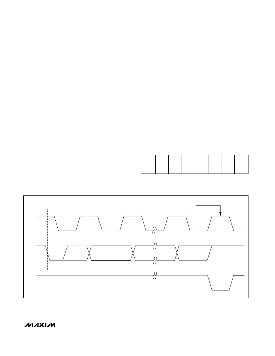
Acknowledge
The acknowledge bit (ACK) is the 9th bit attached to any
8-bit data word. The receiving device always generates
an ACK. The MAX6870/MAX6871 generate an ACK
when receiving an address or data by pulling SDA low
during the 9th clock period (Figure 5). When transmitting
data, such as when the master device reads data back
from the MAX6870/MAX6871, the MAX6870/MAX6871
wait for the master device to generate an ACK.
Monitoring ACK allows for detection of unsuccessful
data transfers. An unsuccessful data transfer occurs if
the receiving device is busy or if a system fault has
occurred. In the event of an unsuccessful data transfer,
the bus master should reattempt communication at a
later time. The MAX6870/MAX6871 generate a NACK
after the slave address during a software reboot, while
writing to the EEPROM, or when receiving an illegal
memory address.
Slave Address
The MAX6870/MAX6871 slave address conforms to the
following table:
MAX6870/MAX6871
EEPROM-Programmable Hex/Quad
Power-Supply Sequencers/Supervisors with ADC
______________________________________________________________________________________
35
SCL
1
S
2
8
9
SDA BY
TRANSMITTER
SDA BY
RECEIVER
START
CONDITION
CLOCK PULSE FOR ACKNOWLEDGE
Figure 5. Acknowledge
X = Don’t care.
SA7
(MSB)
SA6
SA5
SA4
SA3
SA2
SA1
SA0
(LSB)
1
0
1
0
A1
A0
X
R/W