Figure 15, Ure 15), Th7887a – Rainbow Electronics TH7887A User Manual
Page 16
16
TH7887A
2146A–IMAGE–05/02
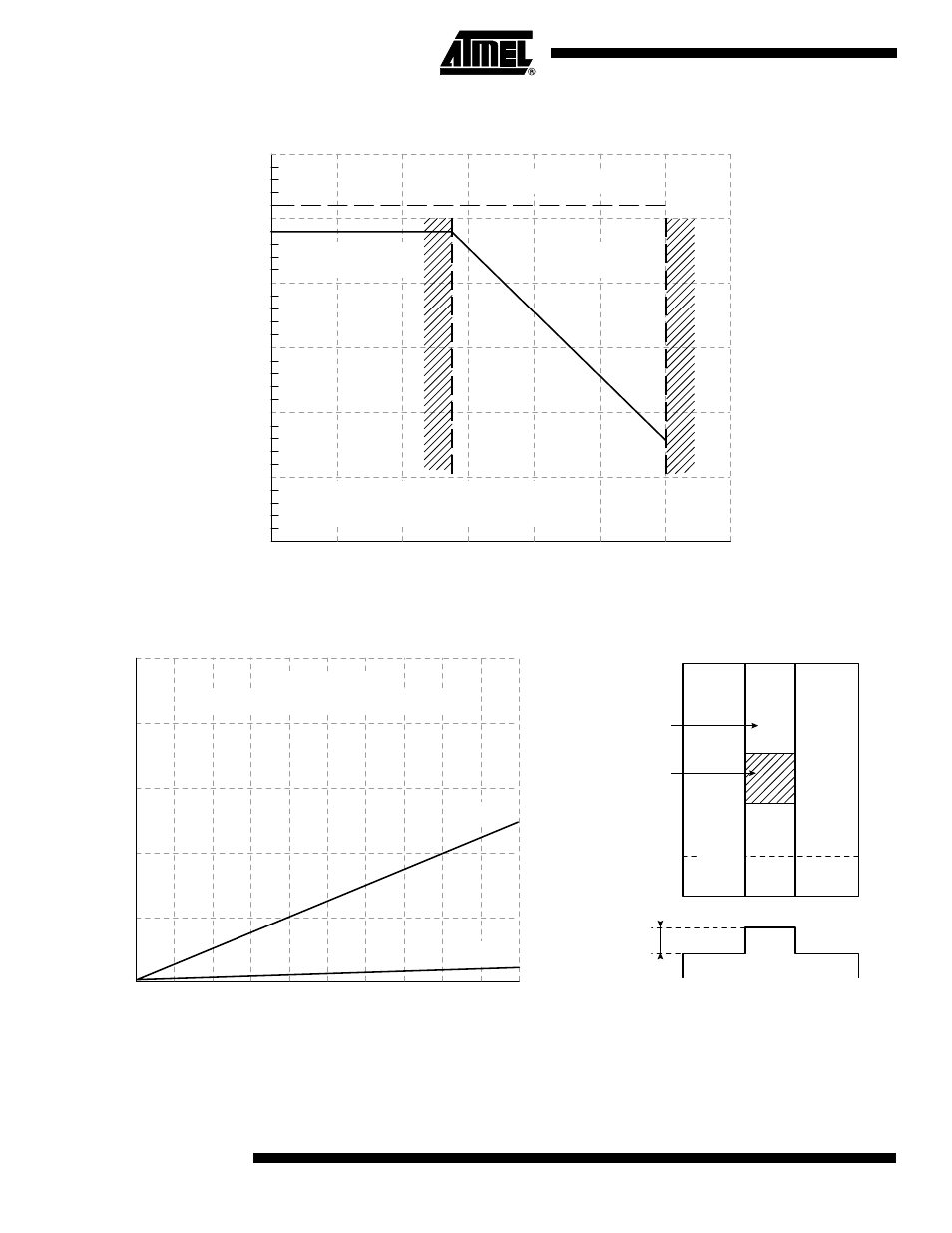
Figure 15. Saturation Level Limitation by the Antiblooming Effect on the Pixel
Figure 16. Smearing Effect
0
2
3
4
5
6
ΦA High Clock Level (Volts)
Saturation Output Level (Volts)
7
8
9
1
0.5
1.5
2
2.5
3
Readout stage limit
Inefficient
antiblooming
Efficient
antiblooming
1.2 MHz
vertical transfer frequency
0
0
1
2
3
4
5
6
Overilluminated Zone (% Image Height)
Smearing/Vsat (%)
7
8
9
10
40
20
60
80
100
60 images / sec.
1.2 MHZ vertical tranfer frequency
100xEsat
a
Smearing level
a,b signal line
Vertical smearing
Overillumination
b
10xEsat