Pin description – Rainbow Electronics MAX14514 User Manual
Page 8
MAX14514
Dual Electroluminescent Lamp Driver
8
_______________________________________________________________________________________
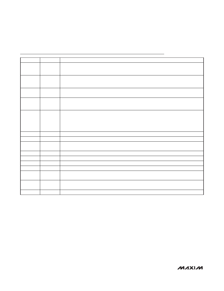
Pin Description
PIN
NAME
FUNCTION
1
DIM1
High-Voltage Output 1 Dimming Control. Apply a PWM signal, DC analog control signal, or connect a
resistor from DIM1 to GND to adjust V
1
peak-to-peak output voltage. Drive DIM1 high or leave DIM1
unconnected to set V
1
to full brightness level.
2
DIM2
High-Voltage Output 2 Dimming Control. Apply a PWM signal, DC analog control signal, or connect a
resistor from DIM2 to GND to adjust V
2
peak-to-peak output voltage. Drive DIM2 high or leave DIM2
unconnected to set V
2
to full brightness level.
3
CAP
Turn-On Time Input. For fast turn-on mode, connect CAP to V
DD
. For slow turn-on/-off mode, connect a
capacitor from CAP to GND to set the turn-on/-off time. t
ON/OFF
= 0.27 x C
CAP
x R
SLEW
.
4
EL
EL Voltage Switching Frequency. Connect an external capacitor, C
EL
, from EL to GND or drive EL with
an external oscillator to set the switching frequency of the V
1
and V
2
high-voltage outputs. Connect EL
to GND to shut off the EL oscillator.
5
SW
Boost Converter Switching Frequency. Connect an external capacitor, C
SW,
from SW to GND or drive
with an external oscillator to set the switching frequency of the boost converter. Connect SW to GND to
shut off the boost oscillator. To avoid LX shorting to GND and causing an increase in internal die
temperature, do not keep SW high. The MAX14514 is protected by entering a thermal-shutdown state.
(See the Thermal Short-Circuit Protection section.)
6
V
DD
Input Supply Voltage
7
GND
Ground
8
LX
Internal Switching DMOS Drain Connection. Connect LX to a switching inductor and an anode of a
rectifying diode.
9
CS
H i g h- V ol tag e Feed b ack C onnecti on. C onnect C S to outp ut of b oost conver ter ( cathod e of r ecti fyi ng d i od e) .
10
COM
High-Voltage EL Panel Common Output. Connect COM to common side of EL lamp.
11
V
2
High-Voltage EL Panel Output 2. Connect V
2
to non-COM
side of EL lamp 2.
12
V
1
High-Voltage EL Panel Output 1. Connect V
1
to non-COM side of EL lamp 1.
13
EN
Enable Input. Drive EN > V
IH_EN
to turn on the device. Drive EN < V
IL_EN
to turn off the device (see the
Shutdown section).
14
SLEW
High-Voltage Slew-Rate Control. Connect an external resistor, R
SLEW
, from SLEW to GND to set the
slew rate of the high-voltage outputs V
1
and V
2
.
⎯
EP
Exposed Pad. Connect EP to GND.