Dual electroluminescent lamp driver, Detailed description, Table 1. slow turn-on, slow turn-off – Rainbow Electronics MAX14514 User Manual
Page 10
MAX14514
Detailed Description
The MAX14514 high-voltage DC-AC converter is
designed to drive two EL lamps. The MAX14514 fea-
tures a +2.7V to 5.5V input range that allows the device
to accept a wide variety of voltage sources, including
single-cell Li+ batteries. The lamp outputs of the device
generate up to 300V
P-P
for maximum lamp brightness.
The slew rate, frequency, and peak-to-peak voltage of
the MAX14514 EL lamp outputs are programmed
through a combination of external components and/or
logic inputs.
Output Slew Rate
The MAX14514 uses the resistor R
SLEW
to set a refer-
ence current for the internal circuitry. The reference
current directly affects the slew rate of the EL lamp out-
put. Increasing the value of R
SLEW
decreases the slew
rate, and decreasing the value of R
SLEW
increases the
slew rate. (See the
R
SLEW
Resistor Selection
section on
how to select R
SLEW
.)
Output Frequency
The MAX14514 uses an internal oscillator to set the
desired output frequency. The output frequency is
adjusted by either 1) the combination of a resistor from
SLEW to GND and an external capacitor from the EL
input to GND, or 2) by driving a clock signal directly
into the EL input. (See the
C
EL
Capacitor Selection
sec-
tion for choosing the C
EL
capacitor value.)
Dimming Control
The MAX14514 features dimming control inputs, DIM1
and DIM2, to control the peak-to-peak voltages on lamp
outputs V
1
, V
2
, and COM. DIM_ is controlled by either a
DC voltage, a PWM signal, or a resistor from DIM_ to
GND. (See the
R
DIM
Resistor Selection
section.)
Applying a DC voltage to DIM_ ranging from V
LPD
to
V
IH_DIM_
linearly varies the corresponding output volt-
age from 130V to 300V. Increasing the voltage on DIM_
increases the peak-to-peak output, and decreasing the
voltage on DIM_ decreases the peak-to-peak output
voltage. Note that when V
DIM_
goes below V
IL_DIM_
, the
corresponding output turns off.
DIM_ features an internal lowpass filter to allow a PWM
signal to control the output voltage. Voltages on DIM_
are internally level translated down to V
IH_DIM_
, so that
the equivalent voltage on DIM_ is (%duty cycle) x
V
IH_DIM_
. The DIM_ inputs accept the 200kHz to 1MHz
frequency range. Note that for PWM signals, the logic
voltage applied to DIM_
_
must be greater than or equal
to V
IH_DIM_
.
The peak-to-peak EL lamp output voltage is related to
V
DIM_
(for V
DIM_
> V
IL_DIM_
) or PWM duty cycle by the
following equation:
V_ - V
COM
= 260 x (V
DIM_
) = 260 x (%duty cycle) x
(V
IH_DIM_
)
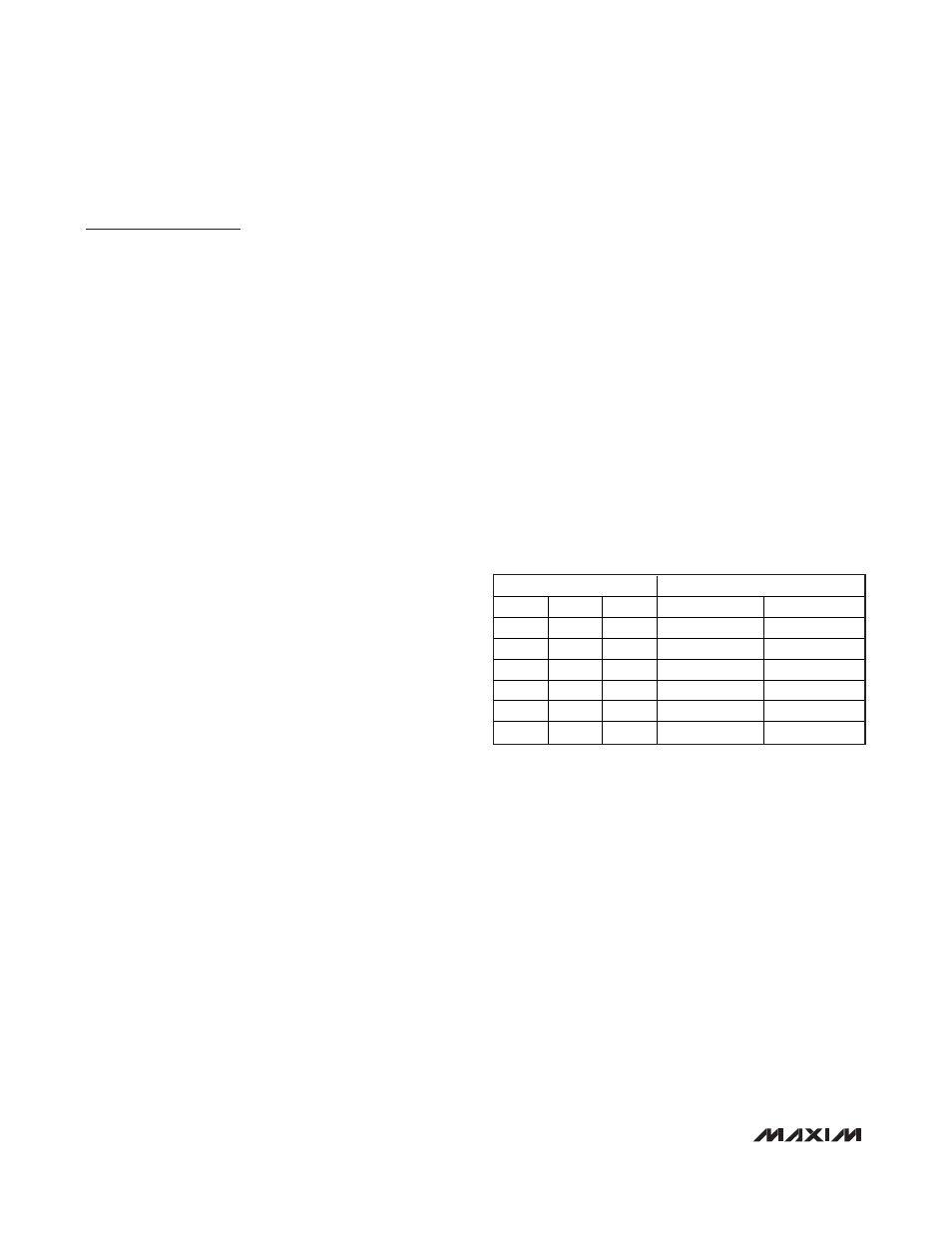
Slow Turn-On, Slow Turn-Off
The MAX14514 provides a slow turn-on and slow turn-
off time feature that is enabled by connecting a capaci-
tor from CAP to GND (see the
Typical Application
Circuit
and the
C
CAP
Capacitor Selection
section). This
slow turn-on/-off feature causes the peak-to-peak volt-
age of the EL outputs to slowly rise or fall any time the
outputs are enabled or disabled, either through EN or
DIM_ (see Table 1). The slow rise and fall of the peak-
to-peak EL output voltage creates a soft fade-on and
fade-off of the EL lamp, rather than an abrupt change in
brightness. To disable the slow turn-on/turn-off feature,
connect CAP to V
DD
.
Boost Converter
The MAX14514 boost converter consists of an external
inductor from V
DD
to the LX input, an internal DMOS
switch, an external diode from LX to the CS output, an
external capacitor from the CS output to GND, and the
EL lamps, C
LAMP1
and C
LAMP2
, connected to the EL
lamp outputs. When the DMOS switch is turned on, LX
is connected to GND, and the inductor is charged.
When the DMOS switch is turned off, the energy stored
in the inductor is transferred to the capacitor C
CS
and
the EL lamps.
Note: Keeping SW high shorts LX to GND and causes
the internal die temperature to increase. The MAX14514
is protected by entering a thermal-shutdown state (see
the
Thermal Short-Circuit Protection
section).
Dual Electroluminescent Lamp Driver
10
______________________________________________________________________________________
LOGIC INPUT
EL OUTPUTS*
EN
DIM1
DIM2
V
1
V
2
1
≥ 0
1
1
Slow Turn-Off
Slow Turn-Off
0
≥ 1
1
1
Slow Turn-On
Slow Turn-On
1
1
≥ 0
X
Slow Turn-Off
X
1
0
≥ 1
X
Slow Turn-On
X
1
X
1
≥ 0
X
Slow Turn-Off
1
X
0
≥ 1
X
Slow Turn-On
Table 1. Slow Turn-On, Slow Turn-Off
*
With capacitor from CAP to GND (CAP is not connected to V
DD
).
X = Don’t Care.