Installation and setup – Cobalt Digital COMPASS 9085 Loudness Processor User Manual
Page 35
9085-OM (V4.3)
9085 PRODUCT MANUAL
2-9
Installation and Setup
Installing a Rear I/O Module
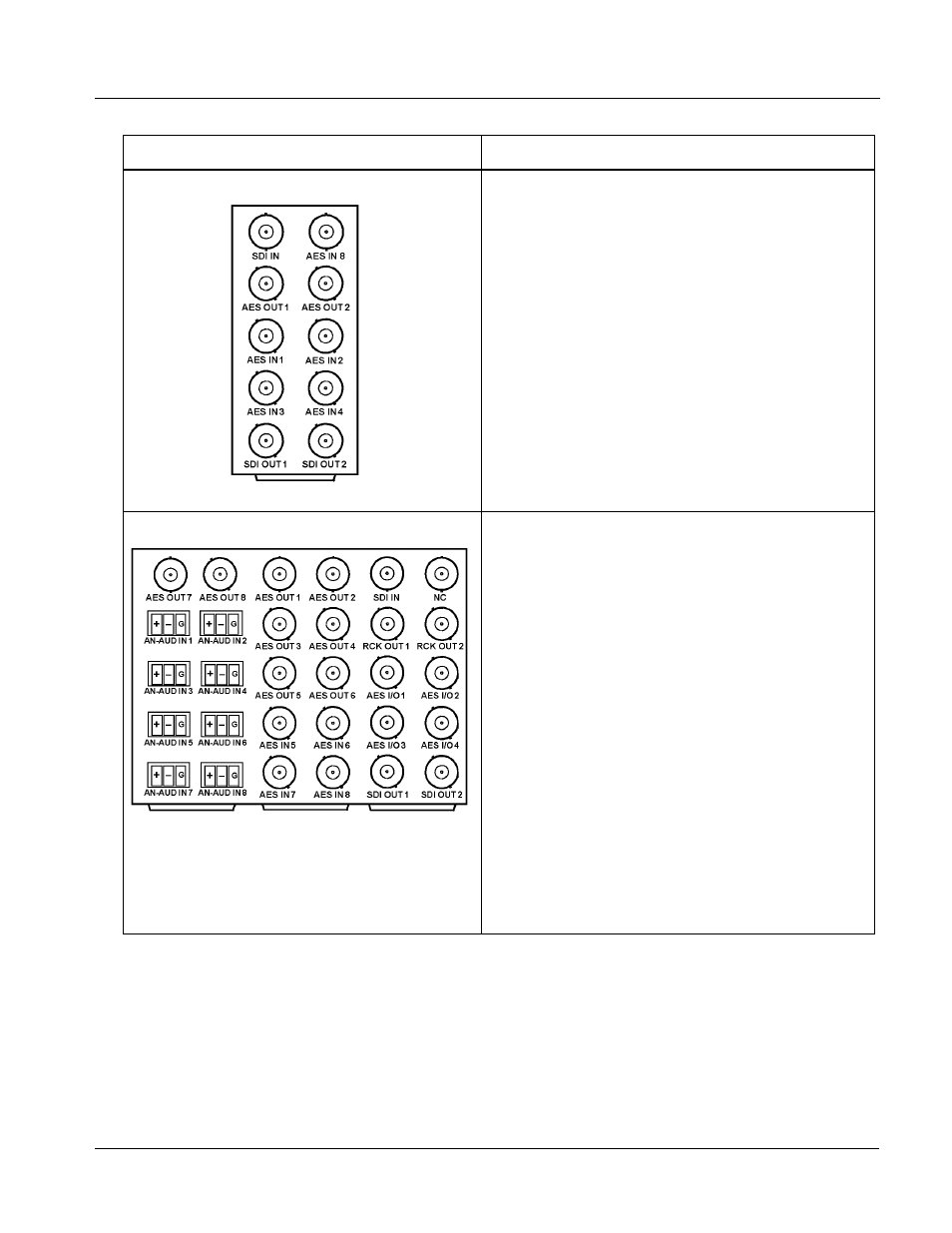
RM-9085-F
Provides the following connections:
• HD/SD-SDI coaxial input (SDI IN)
• Five AES coaxial inputs (AES IN 1 thru AES IN 4;
AES IN 8)
• Two dedicated AES coaxial audio outputs
(AES OUT 1 and AES OUT 2)
• Two buffered SDI coaxial outputs (SDI OUT)
Note: For AES IN 1 thru AES IN 4 on RM-9085-F
Rear I/O Module to function as inputs, AES I/O
switches S11 – S14 must be set to Input
(factory default).
See Setting I/O Switches for AES I/O (1-4)
Ports (p. 2-1) for more information.
RM-9085-G
Provides the following connections:
• HD/SD-SDI coaxial input (SDI IN)
• Two HD/SD-SDI reclocked input copies
(RCK OUT)
• Four AES I/O coaxial input/outputs (AES I/O 1 thru
AES I/O 4; I/O function of each connection is
user-configurable)
• Four dedicated AES coaxial audio inputs
(AES IN 5 thru AES IN 8)
• Eight dedicated AES coaxial audio outputs
(AES OUT 1 thru AES OUT 8)
• Eight analog balanced audio inputs (AN-AUD IN 1
thru AN-AUD IN 8)
• Two buffered SDI coaxial outputs (SDI OUT)
Note: For AES I/O 1 thru AES I/O 4 on RM-9085-G
Rear I/O Module to function as inputs, AES I/O
switches S11 – S14 must be set to Input
(factory default).
See Setting I/O Switches for AES I/O (1-4)
Ports (p. 2-1) for more information.
Table 2-1
9085 Rear I/O Modules — continued
9085 Rear I/O Module
Description