Installing a rear i/o module, Installing a rear i/o module (p. 2-5), Installation and setup – Cobalt Digital COMPASS 9033 Input Processing Analog to Digital Video User Manual
Page 33
9033-OM (V4.0)
9033 PRODUCT MANUAL
2-5
Installation and Setup
Installing a Rear I/O Module
Installing a Rear I/O Module
Note:
This procedure is applicable only if a Rear I/O Module is not currently
installed in the slot where the 9033 is to be installed.
If installing the 9033 in a 8310-C-BNC or 8310-BNC frame (which is
pre-equipped with a 100-BNC rear I/O module installed across the entire
backplane) or a slot already equipped with a suitable I/O module, omit this
procedure.
The full assortment of 9033 Rear I/O Modules is shown and described in
9033 Rear I/O Modules (p. 2-6). Install a Rear I/O Module as follows:
1.
On the frame, determine the slot in which the 9033 is to be installed.
2.
In the mounting area corresponding to the slot location, install
Rear I/O Module as shown in Figure 2-2.
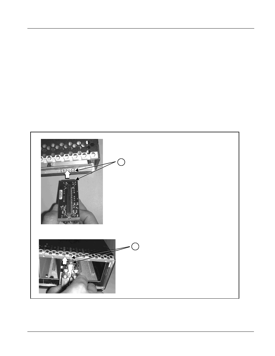
Figure 2-2 Rear I/O Module Installation
DSCN3483A.JPG
Align and engage mounting tab on Rear
I/O Module with the module seating slot
on rear of frame chassis.
Hold top of Rear I/O Module flush against
frame chassis and start the captive screw.
Lightly tighten captive screw.
DSCN3487A.JPG
Note: Rear I/O Modules RM-9033-C, -D, -E, and -H occupy two
rear module slot mounting locations and use two captive
screws.
Rear I/O Module RM-9033-G occupies three rear module
slot mounting locations and uses three captive screws.
1
2