Front panel – Moog Music 500 Series Analog Delay User Manual
Page 5
5
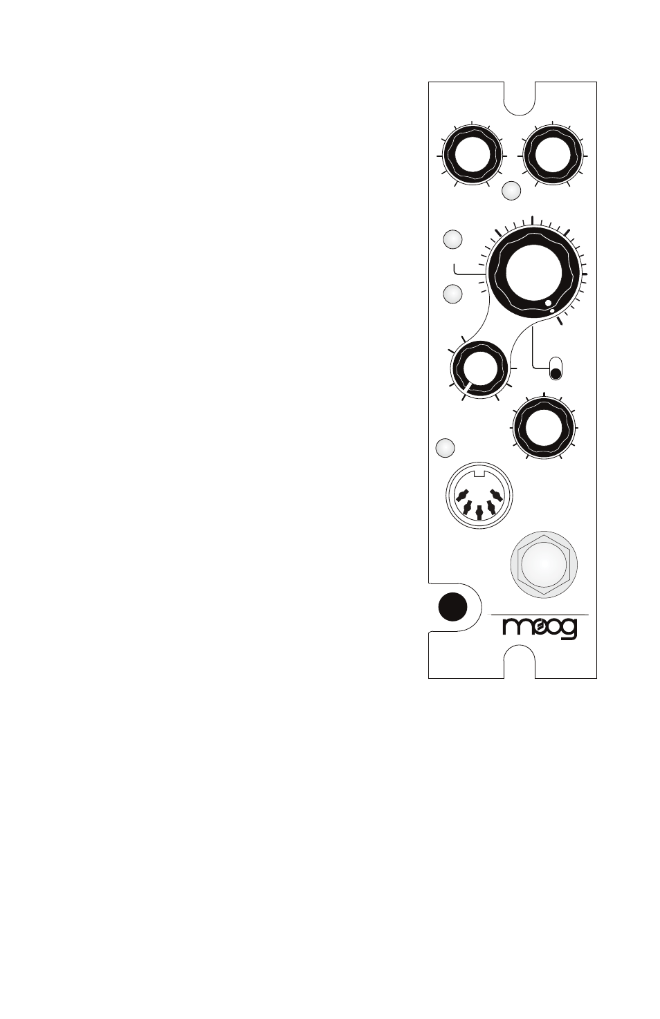
FRONT PANEL
DRIVE:
Sets the input sensitivity of the Analog
Delay providing a 30dB range of adjustment for
optimum signal path, level matching, or over-
driven sounds.
LEVEL LED:
Works in conjunction with the
DRIVE control.
RED
indicates clipping (this can
be used for adding color).
ORANGE flashes
indicate the start of limiting.
GREEN indicates the presence of signal at or
below the nominal level. Steady
GREEN with
brief, occasional
ORANGE flashes indicates the
nominal signal level for best signal-to-noise
ratio.
OUTPUT: Allows gain or attenuation of the out-
put signal for level optimization. The
OUTPUT
control is designed so that an overall boost,
attenuation or unity gain state can be achieved
with any
DRIVE setting.
TIME LED:
•Flashes
RED to indicate the DELAY TIME is
controlled by the TIME knob or via MIDI.
•Flashes
GREEN once indicating the Tap Tempo
destination is set to DELAY TIME. Flashes
GREEN when synced to tap tempo beat.
•Flashes
ORANGE when synced to MIDI clock.
LFO LED:
•Flashes
RED to indicate LFO RATE and
SHAPE, with the transition between on and off
states indicating the selected WAVEFORM.
•Flashes GREEN once indicating the Tap Tempo
destination is set to LFO RATE. Flashes
GREEN
when synced to tap tempo beat.
•Flashes
ORANGE when synced to MIDI clock.
TIME KNOB: Adjusts delay times from 35-
400mS (0.5x setting) and 70-800mS (1.0x set-
ting).
NOTE: Also controllable with the plug-in/
stand-alone editor or via MIDI message. See
separate sections on Tap Tempo and Control
Voltage.
A N A L O G D E L AY
LEVEL
LFO
TIME
0.5x
1.0x
400
mS
800
mS
200
mS
80
mS
FEEDBACK
8
∞
0
2
4
MIDI
TAP/CV
DRY
WET
OUTPUT
0
4
6
10
0
4
6
10
DRIVE
BYPASS