Stereo linking two analog delay units – Moog Music 500 Series Analog Delay User Manual
Page 20
20
MIDI CLOCK SYNC: The DELAY TIME and LFO RATE can be synchronized
to MIDI System Real-time Clock messages. These messages are 24 ppq. To
enable sending of these messages, consult the user manual for your MIDI
device. When the Analog Delay receives MIDI Clock messages, the LED
indicator for the synchronized function turns orange to indicate that it is
synchronized to MIDI Clock. The
DELAY TIME and LFO RATE can be set to
divisions of this tempo via the front panel (Delay
TIME only), the editor, or
from MIDI CCs# 77 and 79 (see Clock Divisions table).
MIDI SYSEX MESSAGES: Used for updating or finding out the unit’s firm-
ware version. For more information about this, refer to user notes with any
firmware updates posted in the Analog Delay section of the www.moog-
music.com website.
STEREO LINKING TWO ANALOG DELAY UNITS
The included Stereo Linking Kit allows you to link two units together via
special stereo linking cable. With two Delays linked, one device becomes
the master and the other the slave.
•In a stereo-linked pair of Analog Delays, the master device controls the
slave device’s:
DELAY TIME, TIME RANGE (0.5x/1.0x), FEEDBACK, LFO
RATE, LFO SHAPE, and LFO AMOUNT settings
•
DRIVE, OUTPUT, and MIX controls are analog, independently controlled
and not linked.
•The
TAP/CV Input works across the stereo link from the master to the
slave only.
•All MIDI messages received by the master will be echoed to the slave with
the exception of MIDI system exclusive (SysEx) messages
INSTALLATION
Please note that the end of the stereo linking cable connector designed to
attach to the slave device has an additional wire loopback.
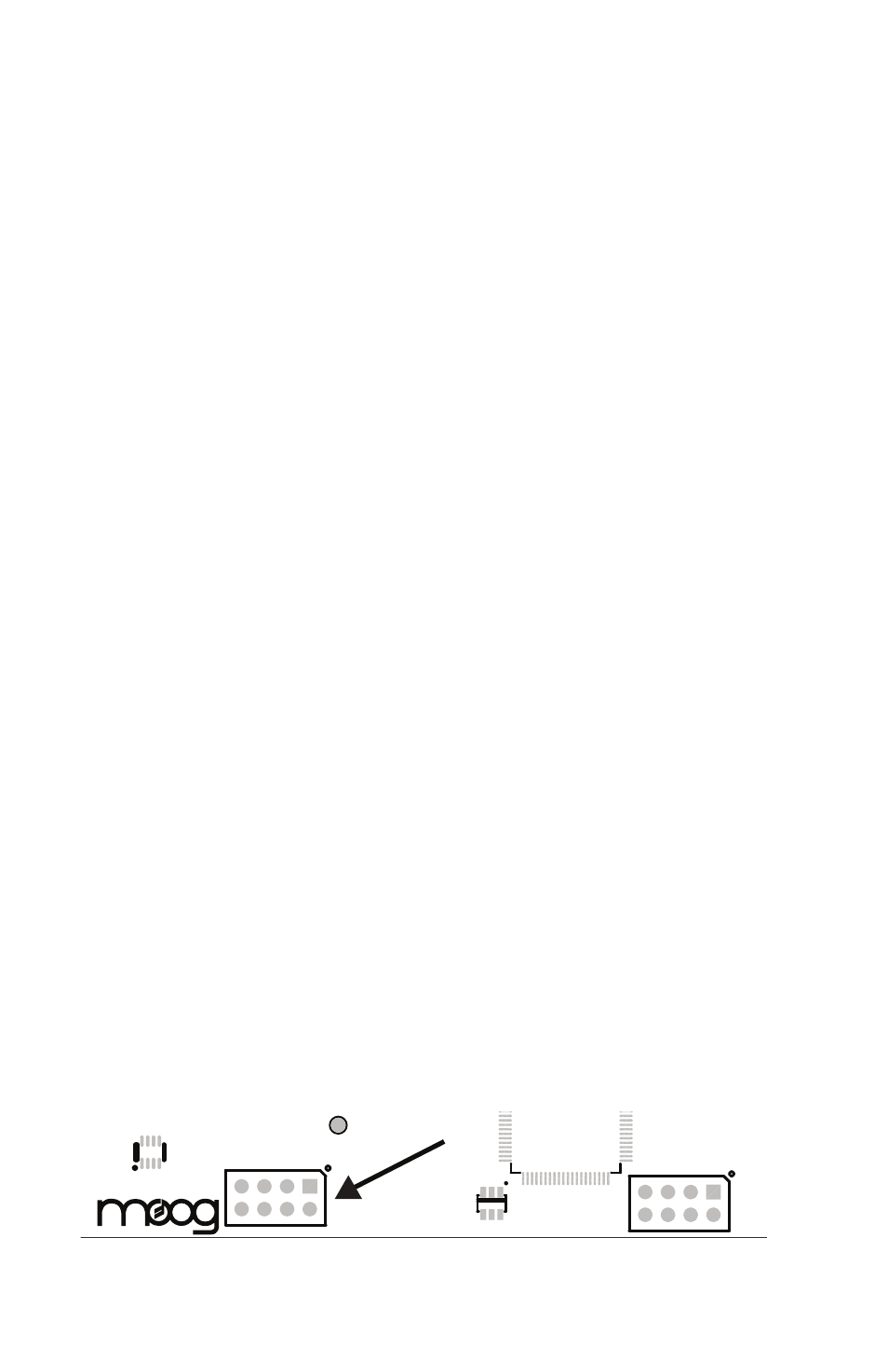
• Locate the expansion connector labeled J3 on the bottom center edge of
the Analog Delay circuit boards.
• When plugging in the cable, the red stripe must face the rear edge of the
Analog Delay Module. (The edge that plugs into the chassis)
• Plug the end without the wire loop into the Delay you wish to be the
master unit.
• Plug the end with the wire loop into the slave unit.
When two units are linked in stereo mode the
TIME and FEEDBACK
con-
trols on the slave unit will be disabled.
JTAG
CLK
EXPANSION
U10
J3
U13
U22
J6
TP11