Figure 2: front panel (technical adjustments) – Electronics FC-24 User Manual
Page 9
9
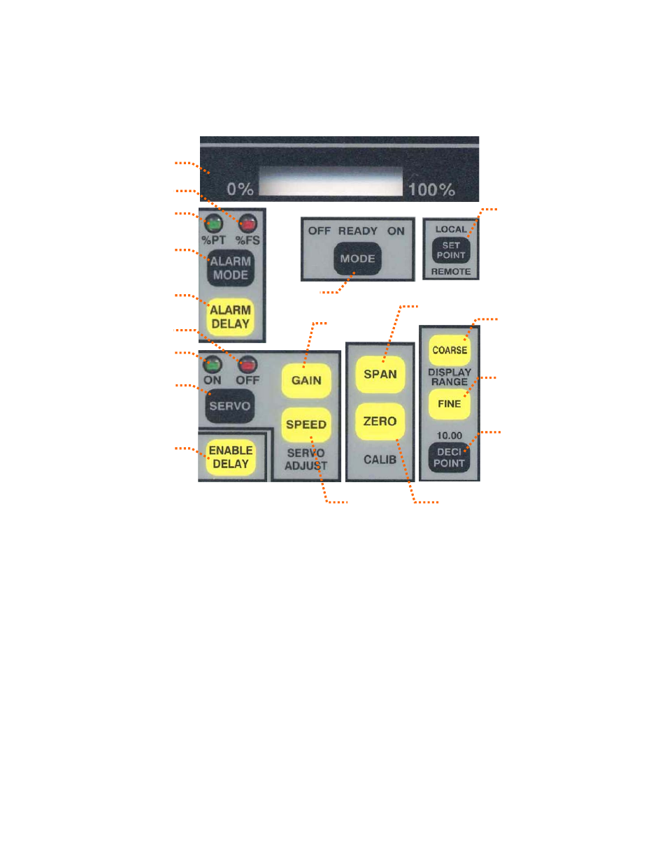
FIGURE 2: FRONT PANEL (Technical Adjustments)
2-15
2-14
2-13
2-16
2-17
2-22
2-27
2-19
2-18
2-21
2-20
2-28
2-29
2-30
2-25
2-26
2-23
2-24
2-13
MagnaValve output signal level
2-22 Control Mode button
2-14
Alarm bandwidth % of full scale
2-23 Servo Gain button
2-15
Alarm bandwidth % of setpoint
2-24 Servo Speed button
2-16
Alarm mode button
2-25 Span button for amperage calibrate
2-17
Alarm delay button
2-26 Zero button for zero amperage
2-18
Servo “Off” LED indicator
2-27 Setpoint
local/remote
button
2-19
Servo “On” LED indicator
2-28 Coarse Display Range
2-20
Servo On-Off button
2-29 Fine Display Range
2-21
Enable Delay button
2-30 Decimal Point
FRONT PANEL
(lower portion with plate removed)
See also other documents in the category Electronics Relay:
- Pot-24 (2 pages)
- WM 3000-24 (2 pages)
- WM 3000-24 (10 pages)
- 500-P (10 pages)
- 500-P (2 pages)
- LP2000VAR (2 pages)
- FC (2 pages)
- FC (21 pages)
- LP2000_VAR (2 pages)
- LP2000_VAR (13 pages)
- VLP1000_VAR (2 pages)
- LP-24 (2 pages)
- LP-24 (15 pages)
- 576-24 (2 pages)
- AC (2 pages)
- AC (25 pages)
- 578-24 (2 pages)
- 590 (8 pages)
- 590 (2 pages)
- 590-24 (2 pages)
- 590-24 (26 pages)
- 577 (2 pages)
- FC-24 (2 pages)
- 190-AC (2 pages)
- 100 (2 pages)
- VLP-24 (2 pages)
- 0-120 Vac Variac (1 page)
- AC-24 (16 pages)
- AC-24 (2 pages)
- MC (12 pages)
- MC (2 pages)
- 179-AC (2 pages)
- VLP1000 (2 pages)
- 580-24 (2 pages)
- 178-DC (2 pages)
- 577-24 (2 pages)
- 500-24 (6 pages)
- 500-24 (2 pages)
- 180-AC (2 pages)
- LP2000 (2 pages)
- VLP1000VAR (2 pages)