Electronics FC-24 User Manual
Page 3
3
1.PRODUCT DESCRIPTION
The Model FC-24 Shot Flow Controller will measure and control the rate of flow of steel shot
passing through a special normally closed magnetic valve called a MagnaValve. A digital dis-
play is provided for indications of shot flow rate. A 0-10 Volt dc output signal representing
flow rate is available for remote indication or strip-chart recording. High and low alarms are
set to bracket the requested shot flow rate. The alarm bandwidth, for either percent of full
scale or percent of setpoint, is adjustable from the front panel. Either local (front panel) or re-
mote (0-10Vdc) set point commands may be used.
2.THEORY OF OPERATION
The MagnaValve uses permanent magnets to hold the shot and electro-magnets to cancel the
magnetic field. When power is applied to electro-magnets the shot is free to flow. The desired
flow rate command or setpoint is compared to the actual flow rate and a control signal is sent
to the MagnaValve to achieve desired flow rate. If the desired flow rate is not achieved within
an adjustable time period, then a high/low alarm relay will be triggered. This output signal may
be used to inhibit further machine operations and signal the operator. The FC Controller can
be used with any MagnaValve with built-in flow rate sensors, which have a 0- 10 Vdc output
signal.
3.LOCATION OF ADJUSTMENTS
For location of adjustments see Figures 1 and 2. Numbers in parenthesis (figure-balloon) rep-
resent figure number and balloon call-out number. For example, digital display is (1-3), mean-
ing figure 1 and balloon number 3. Notice that the yellow buttons also require the use of the
▲or ▼ buttons to change the display readings. The black buttons act alone to change the
status of a function.
4.PRELIMINARY ADJUSTMENTS
A. Apply 24Vdc power.
B. Zero: The display (1-1) should read 0.0 during no-flow condition. If the digital display does
not show zero then push the “Zero” button (2-26).
C. Calibration of the display range may be required. Use the arrow buttons to adjust the dis-
play to read 0.0 Other full-scale values may be used with different MagnaValves. Push
the “Display Coarse” button (2-28) to show the current value of full scale range. To change
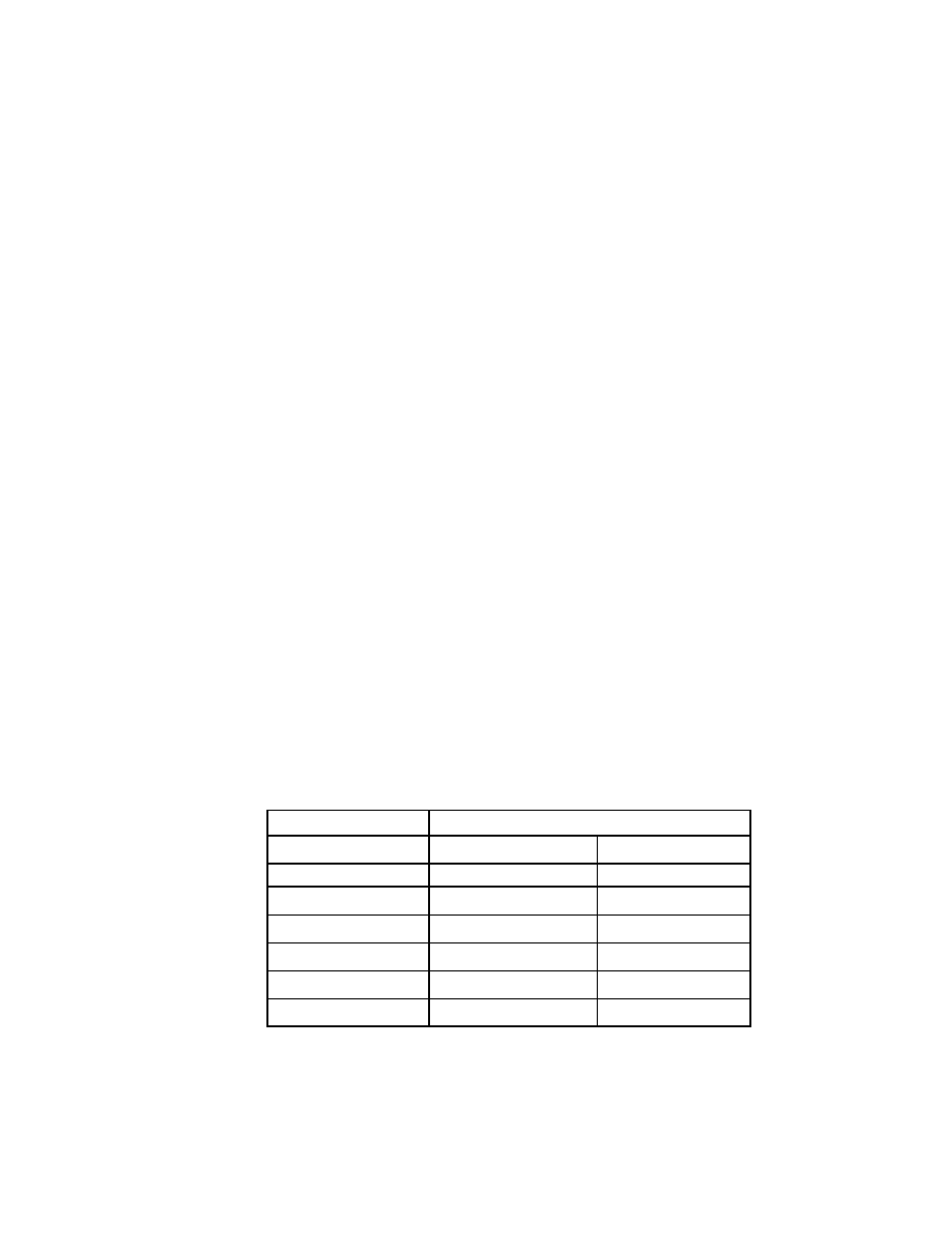
the range use the ▲or ▼ buttons. The following table shows available scaled settings.
MagnaValve Flow
Range
576-24
2 Lbs/min
1 Kg/min
577-24
10 Lbs/min
5 Kg/min
578-24
20 or 30 Lbs/min
10 or 15 Kg/min
579-24
100 Lbs/min
45 Kg/min
580-24
200 Lbs/min
100 Kg/min
590-24
300 Lbs/min
150 Kg/min
500-24
700-1200 Lbs/min 300-600 Kg/min
Note: MagnaValves are calibrated to give a 0-10 Vdc output signal at rated flow. Because of calibration
differences caused by shot type and size, custom factory calibration is recommended .Please state type of
shot, size of shot and desired flow range from the table above.
Multiple shot sizes may be used with one valve with slight degradation of accuracy. Adjustments for differ-
ent flow ranges can be made by adjusting the “Span” at the MagnaValve or at the FC-24 control.