See table, Electrical power supply, Transformers and wiring voltage drop – Grain Systems PNEG-1458 User Manual
Page 20: Power supply disconnect, Machine to earth grounding, Dryer installation
4. Dryer Installation
20
PNEG-1458 T-Series Tower Dryer
Fuel System Recommendations
Electrical Power Supply
An adequate power supply and proper wiring are important factors for maximum performance and long
life of the dryer. Electrical service must be adequate enough to prevent low voltage damage to motors and
control circuits.
Transformers and Wiring Voltage Drop
Advise the service representative of the local power supplier that an additional load will be placed on the
line. Check on KVA rating of transformers, considering total horsepower load. The power supply wiring,
main switch equipment and transformers must provide adequate motor starting and operating voltage.
Voltage drop during motor starting should not exceed 14% of normal voltage and after motor is running at
full speed it should be within 8% of normal voltage.
Power Supply Disconnect
All dryers are equipped with a power disconnect switch in the power box to permit total power shut down
before opening the power box door, as required for inspection and service. The power disconnect switch
is located on the power box door for quick shut down.
Machine to Earth Grounding
It is very important that a machine to earth ground rod be installed at the dryer. Place the ground rod that
comes standard, within eight feet (8') of the dryer and attach it to the dryer control panel with at least a #6
solid, bare, copper ground wire and the clamp provided. The grounding rod located at the power pole will
not provide adequate grounding for the dryer. The proper grounding will provide additional safety
in case of any short and will ensure long life of all circuit boards, SCR drive and the ignition system.
The ground rod must be in accordance with local requirements.
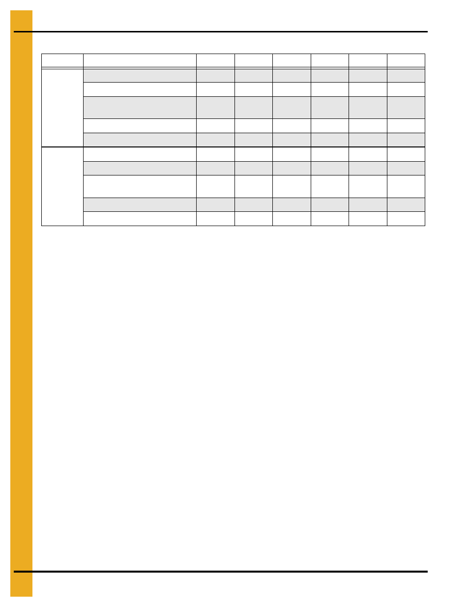
1050
1260
1575
1875
20100
24100
Liquid
Propane
Burner Capacity (Btu/Hr)¹
11100000
11100000
16654000
17669000
21298000
23393000
Maximum Fuel Usage (Gal/Hr)
121
121
182
193
233
255
Recommended Liquid
Line Size (>100')
3/4"
3/4"
3/4"
1"
1"
1"
Fuel Train Orifice Size (inch)
0.625"
0.625"
0.7187"
0.787"
0.781"
0.781"
Pressure Regulator Setting (PSI)
9
9
9
9
9
9
Natural
Gas
Burner Capacity (Btu/Hr)
11100000
11100000
16654000
17669000
21298000
23393000
Maximum Fuel Usage (Cu Ft/Hr)
11100
11100
16654
17669
21298
23393
Recommended Liquid
Line Size (>100')
2"
2"
2-1/2"
2-1/2" 2-1/2"
2-1/2"
Fuel Train Office Size (inch)
0.7187"
0.7187"
0.8125"
0.875"
1.000"
1.000"
Regulated
Supply
Pressure
(PSI)
10
10 10 10 10 10
¹Burner capacity for fuel line sizing. Actual average fuel usage is typically 50%-60% of the burner capacity.