Td-vip-01 data sheet selection – Grain Systems PNEG-1798 User Manual
Page 30
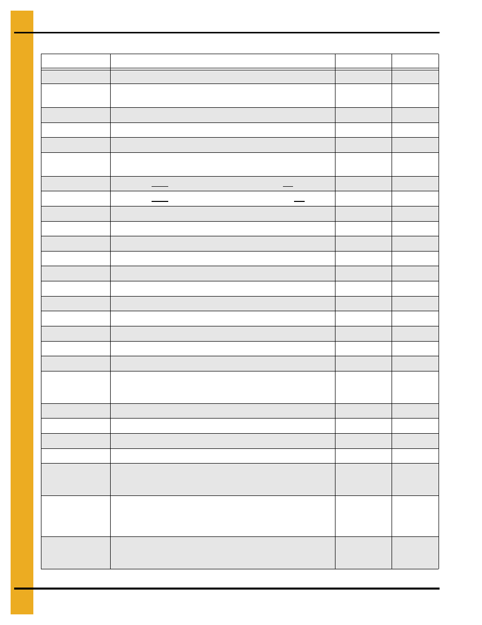
8. TD-VIP-01 Data Sheet Selection
30
PNEG-1798 Tower and T-Series Dryers Vaporizer
Vaporizer Pressure Leak Test Data
Step #
Information
Recorded Data
Initials/Date
Bushing installed to accept the 300 PSIG test gauge.
Regulator connected to nitrogen cylinder and handle or knob
turned fully CCW.
High pressure hose connected to the regulator.
Hose end connected to the 3/4" manual isolation valve input.
Hose ends tightened at regulator and manual valve.
Power cord available and ready to connect to the 3/4" ASCO
solenoid valve wires.
Power cord black wire connected to one of the ASCO red wires.
Power cord white wire connected to the remaining ASCO red wire.
Power cord green wire connected to the ASCO green wire.
Power cord 3 prong male end plugged in a live 120V receptacle.
Audible click or popping sound heard at 3/4" ASCO solenoid.
Regulator high pressure gauge pressure reading.
PSIG
3/4" Manual isolation valve ‘CLOSED’.
Regulator low pressure gauge pressure reading.
PSIG
No leaks between nitrogen cylinder and input of 3/4" manual valve.
Test gauge reading with 3/4" manual valve ‘CLOSED’.
PSIG
Test gauge reading with 3/4" manual valve ‘OPEN’.
PSIG
Number of leaks initially found before repairs.
Leaks
Leaks of
repaired (If applicable).
1. Regulator adjusted to test pressure.
2. 0 Minute test time.
1. ______ PSIG
2. ______ Time
3/4" Manual isolation valve ‘CLOSED’.
Nitrogen cylinder supply valve ‘CLOSED’.
Regulator vented and no pressure indicated on regulator gauges.
Test gauge pressure reading during this step.
PSIG
1. Test pressure of
.
2. 3 Minute test time after time of
.
1. ______ PSIG
2. ______ Time
‘As found’
beginning of
3 minutes
1. Regulator adjusted to test pressure.
2. 0 Minute test time.
1. ______ PSIG
2. ______ Time
‘As left’ end of
3 minutes
1. Regulator adjusted to test pressure.
2. 0 Minute test time.
1. ______ PSIG
2. ______ Time