Rough Country 675-76-81.20 User Manual
Page 2
1. Jack up the front of the vehicle and support the vehicle with jack stands, so that the front wheels are off the ground
2. Remove the front tires/wheels.
3. Remove front shocks
4. Remove front u-bolts and nuts.
5.
Raise axle housing with floor jack until axle is free from spring. Support axle with floor jack.
6. Remove spring-eye bolts (Retain stock bolts for reuse) from the front springs, and remove springs.
7. Locate supplied bushings and sleeves. Grease bushings and install in #8019. Install new springs, part # 8019 for the
front using factory hardware.
8. Lower axle housing until center pin is located in spring pad.
9. Do not tighten spring bolts until the weight of the vehicle is being supported by the springs. Over-tightening the
spring eye bushings can result in a rough ride and premature bushing failure. Tighten only to make the poly bush-
ings slightly swell.
10. Install new u-bolts and hardware. Tighten u-bolts, alternating from bolt to bolt. Torque ½” u-bolts to 60 ft./lbs. and
9/16” u-bolts to 87 ft. /lbs.
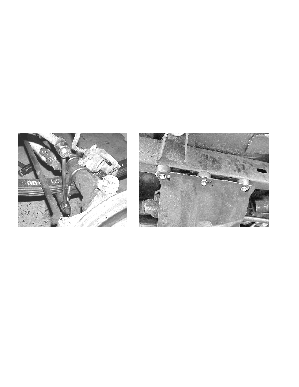
11. On the front of the vehicle assemble new sway bar links with poly bushings and sleeves. The factory hardware will
not be reused on the upper sway bar mount. Use the supplied 12mm x 1.75 x 80mm bolts, washers and nuts for the
upper sway bar mount and reuse the lower factory hardware. See Photo 1.
12. Lower vehicle to the ground and install front shocks.
13.
After the tires and wheels have been installed and the vehicle has been lowered to the ground the transfer case can
be lowered.
14. With a floor jack supporting the transfer case skid plate loosen but do not remove the bolts that secure it to the frame
rail. On the opposite side of the vehicle remove the bolts that secure it to the frame rail.
15. nstall the transfer case spacer in between the transfer case skid plate and the frame rail and install the 3/8” bolts and
washers. See Photo 2
.
Installation Instructions
Photo 1
Photo 2