Rough Country 510.20 User Manual
Page 2
INSTALLATION INSTRUCTIONS
1. If equipped with anti-say bar, disconnect front sway bar bolts on coil mounting seat. (You will reattach after installa-
tion without a need for modification).
2. Remove the brake caliper form the brake rotor and secure out of the way. If the stock rubber units are retained, they
must be in good condition; check for chafed spots, cracks and dry rot.
3. Put transmission in neutral. Place a floor jack under the outer ends of both axle halves and evenly raise vehicle ap-
proximately 12".
4. Place jack stands under frame rails approximately 4" behind radius arm brackets. Ease vehicle down onto stands.
Continue down with jacks until there is only a slight load on the coil springs. Put vehicle in park or gear, set emer-
gency brake and chock rear wheels to prevent any possibility of movement.
5. Remove tires and shock absorbers.
6. If longer brake hoses are being used, disconnect the stock rubber hoses where they connect to the metal lines at the
frame rails. A piece of rubber tubing routed from the metal lines to a catch pan will eliminate a fluid mess. New hoses
are installed in a later step.
7. Remove upper spring retaining clip. Support axle with floor jack at this time. Avoid dropping the axle too far or the
axle shaft will disengage its splines.
8. Remove lower retaining nut and washer. Lower axle to loosen spring. Remove spring by pulling the top outward.
9. Install original shock behind the coil seat. This will hold the beam up while working on the pivot end. Remove cross-
member bolt on driver side beam. Unbolt and remove stock pivot point bracket.
10. Replace with Rough Country pivot bracket. This will be the larger of the two brackets in the kit. Using the two upper
bolt holes and temporarily using stock Ford bolts, attach bracket to cross member. Mark new Rough Country bracket
using existing holes in cross member as a guide. Remove and drill to 1/2" diameter. Refer to illustration #2. DO NOT
OVERLOOK THIS STEP!
11. Replace bracket using only the 4-1/2" x 1-1/2" bolts, washers, and locknuts provided in the kit. Do not use any of the
Ford stock bolts on this bracket. The stock bolts were used just to hold the bracket in place temporarily. tighten the
4-1/2" bolts at this time. (torque to 115 ft. lbs.) See Photo 1.
12. 10. Raise the pivot end of driver side beam into Rough Country bracket. Install re-using stock bolt, washers, and
nut. Tighten at this time (toque to 120-150 ft. lbs)
13. 11. Move on to passenger side, repeat steps 4 through 8.
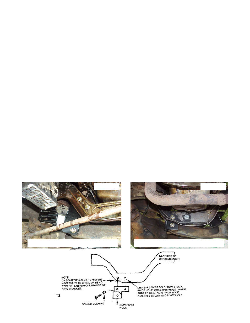
14. Remove pivot bolt for passenger side beam. Mount passenger side bracket into cross member using 9/16" x 3-1/2"
bolt and 1-5/32" spacer. Refer to Photo 2 and Diagram 1. Measure over from stock pivot hole center 3-1/8” on
back side of cross member making sure to keep hole parallel to stock hole and keep the new pivot hole directly be-
low the stock pivot hole in the cross member. Drill a 9/16" hole and install the 9/16" x 1-1/2" bolt washer and locknut
provided. Raise beam and install the 9/16" x 3-1/2" bolt, washers, and locknut through pivot. Tighten the three 9/16"
bolts at this time. (torque to 115 ft. lbs.)
PHOTO 1
PHOTO 2
DIAGRAM 1
Passenger I-Beam Shown in new Bracket
Driver I-Beam Shown in new Bracket