Rough Country RC608 User Manual
Page 4
POST INSTALLATION INSTRUCTIONS
1. Check all fasteners for proper torque. Check to ensure there is adequate clearance between all rotating, mobile,
fixed and heated members. Check steering gear for interference and proper working order. Test brakes.
2. Check to ensure metal brake lines have sufficient slack to eliminate interference and maintain proper working order.
Failure to perform inspections may result in component failure.
3. Readjust headlights to proper settings.
MAINTENANCE INFORMATION
It is the buyers ultimate responsibility to have all bolts/nuts checked for tightness after the first 100 miles and then
every 1000 miles. A qualified professional mechanic must inspect wheel alignment steering system, suspension and
driveline systems at least every 3000 miles.
Thank you for choosing Rough Country for all your suspension needs.
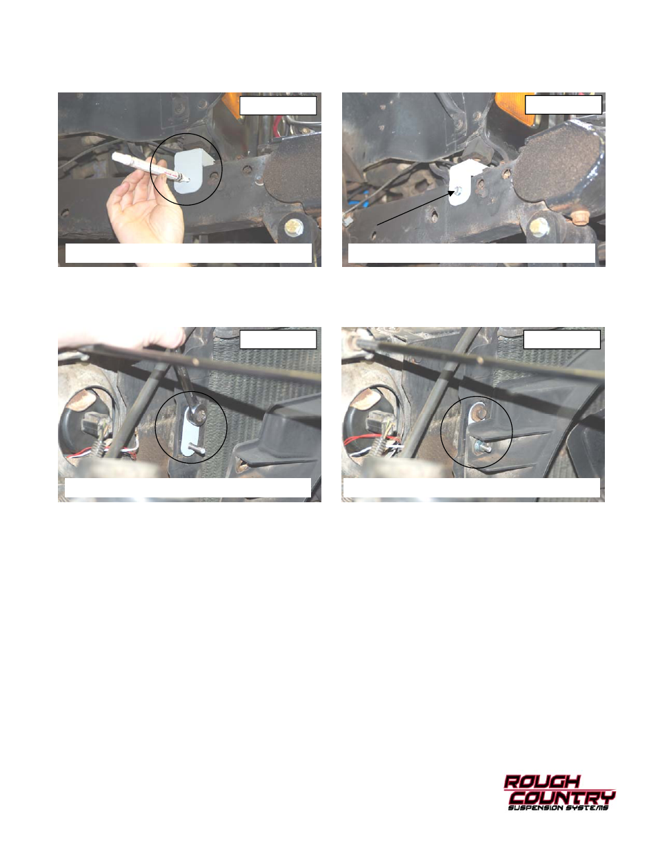
10. Install the new front bump stop extension under the bump stop on radiator core support. Using the bracket as a tem-
plate mark hole to be drilled. See Photo 6.
11. Drill a 1/4” hole in frame and secure using the supplied 5/16” x 1” self tapping bolt and a 13mm socket to tighten.
See Photo 7. Do not over tighten the bolt. Repeat for the opposite side.
12. After all body puck are in tighten all bolts. 19mm socket for the 1/2” bolts and 16mm for the 7/16” bolts.
13. Install the 1/4” clinch studs into radiator drop bracket using hammer and small socket.
14. Install the four radiator fan shroud drop brackets using stock hardware. See Photo 8.
15. Reinstall the shroud on the bracket with the supplied 1/4” lock nuts and flat washers. See Photo 9.
16. Reinstall the coolant reservoir and power steering reservoir to the fan shroud if applicable. Use a 13mm for stock
bolts and 7/16” for new nuts.
17. Reconnect the air intake to the air filter housing and throttle body.
18. Reinstall plastic jeep cover and metal plate using 3/8” socket. Metal plate should go under the body mount. Install
hard brake line back into clips.
19. Re-Check all fastener to confirm all components are not binding or in the way of moving parts.
Photo 6
Photo 7
Photo 8
Photo 9
MARK THE HOLE TO BE DRILLED
INSTALL THE SUPPLIED 5/16” X 1” BOLT
INSTALL THE SHROUD BRACKETS
REINSTALL THE SHROUD TO THE BRACKETS