Rough Country 272N2 User Manual
Page 9
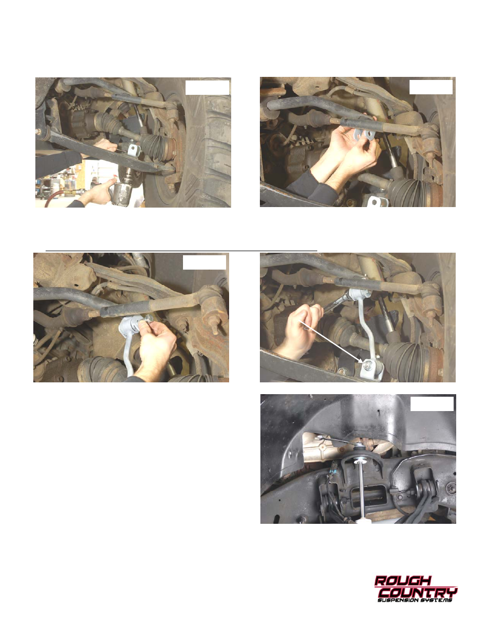
35. Install the tie rod end in the knuckle with the stock hardware and using a 19mm wrench. Tighten to 50 ft.-lbs.
36. Install the supplied sway bar link bracket as shown in Photo 30 on the lower control arm using the supplied 12mm x
35mm bolt and flange lock nut. Tighten using a 18mm & 19mm wrench.
37. Install the upper sway bar link bracket as shown on the sway bar with the supplied 12mm x 35mm Bolt and flange
lock nut. See Photo 31.
38. Install the sway bar link in the upper bracket with the supplied 12mm x 65mm bolt and flange lock nut. See Photo
32. Tighten using a 18mm & 19mm wrench.
39. Install the sway bar link in the lower bracket and secure with the supplied 12mm x 65mm Bolt and flange lock nut.
The bolt will need to be installed as shown with the threads pointing forward. See Photo 33.
40. Using a torsion bar tool, load the torsion bars using the
mark made earlier as a reference.
41. Locate the supplied front shock absorbers and assemble
with bushings/sleeves. Install front shock Part #658734 in
the factory lower location as shown in Photo 31 with factory
hardware and using a 21mm wrench. Install the shock in
the upper mount with supplied stem bushings, cup washers
& nuts using a 9/16” wrench.
42. Install the tires and wheels and jack up the vehicle to
remove the jack stands. Lower the vehicle to the ground.
43. Tighten control arm hardware using a 18mm & 24mm
wrench.
Photo 30
Photo 31
Photo 32
Photo 33