Rough Country 277.20 User Manual
Page 5
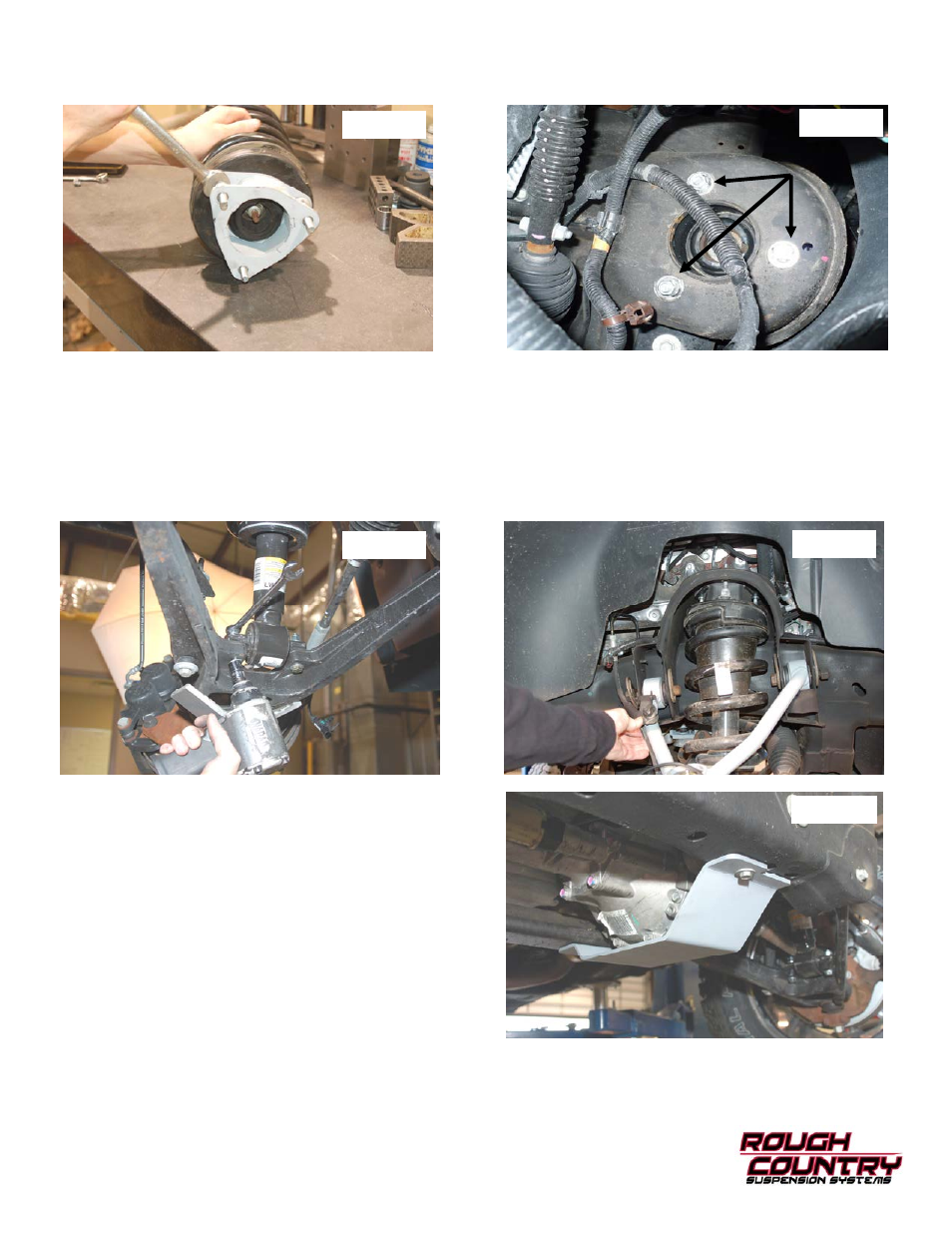
27. Install the strut spacer on the factory strut with factory hardware and using a 18mm wrench.
See Photo 20.
28. Install the strut assembly in the factory mount with the supplied 10mm nuts/washers & lock-washers on the upper
mount. Tighten using a 17mm wrench.
Note: Flat washer must be installed on studs. See Photo 21.
29. Install the strut in the lower control arm using the supplied 3/8
” 2 1/4” bolts /washers & nuts using a 9/16” wrench.
See
Photo 22. It may be necessary to jack up the lower control arm with a floor jack to align lower strut holes.
32. Reinstall the sway bar on the lower control arm using a15mm wrench
.
33. Reinstall the knuckle to the upper control arm with the supplied castle nuts/cotter pins. Tighten using 3/4
” wrench to
50
ft/lbs. DO NOT OVER-TORQUE THE CASTLE NUT. Reinstall the tie rod end into the knuckle with factory hardware
and using a 21mm wench.
34. Reinstall the driveshaft with the factory hardware using a 11mm wrench.
35. Install the brake line bracket on the new control arm with the supplied 1/4
” lock nut / washer and using a 7/16” wrench.
See Photo 23. Driver side shown.
36. Reconnect the ABS wire that was disconnected in Step 6.
37. Locate and install the new lower skid plate below the differen-
tial in the factory location (if equipped) with the factor hard-
ware and using a 15mm wrench.
See Photo 24. If not
equipped with a factory skid plate, use the supplied 3/8
” self
tapping bolts to install the skid plate in the holes in cross-
member.
38. Reinstall the wheels/tires.
39. Jack up the vehicle and remove the jack stands.
40. Lower the vehicle to the ground.
Photo 20
Photo 21
Photo 22
Photo 23
Photo 24