Rough Country 277.20 User Manual
Page 3
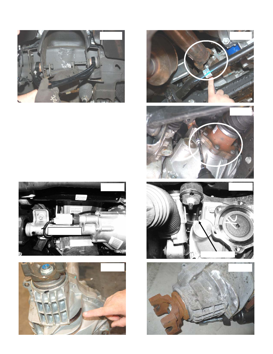
10. Mark location of alignment cams on upper control arms to allow installation of new arm to same position. Using a
21mm wrench and 21mm socket, remove the upper control arms from the vehicle.
See Photo 7. Retain the hardware
11. Using a 11mm wrench, remove the drive shaft bolts.
See Photo 8. Retain hardware for reuse.
12. Place a floor jack under the differential assembly to provide
support for following steps.
13. Using a 15mm wrench, remove the 6 axle shaft bolts and se-
cure axle shafts out of the way.
See Photo 9 Repeat on op-
posite side. Retain the factory hardware for reuse. Unplug the
electrical connector on differential as shown in
Photo 10 and
unplug the diff vent hose
. Photo 11
14. Using a 18mm socket remove the 4 differential bolts (2 each
side) securing the differential to the frame.
See Photo 9.
15. Slowly lower differential assembly to the ground.
16. Using a hand grinder. Grind away marked portion of the cool-
ing fin as shown in
Photo 12 and Photo 13. Grind until flush
with casing.
Photo 7
Photo 8
Photo 9
Electrical Plug
Photo 12
Photo 13
Photo 10
Photo 11
Diff Vent Hose