Rough Country 639P User Manual
Page 5
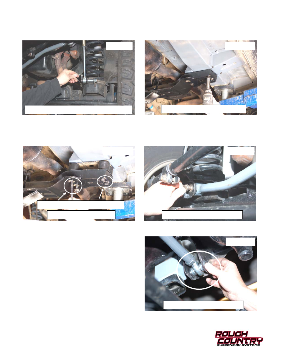
21. Install on the lower axle mounting pin. Install the disconnect pin. See Photo 12. Note: When disconnected the
hitch pin will be used on the upper mount to secure the sway bar link to the mount.
22. Tighten the lower control arm hardware using a 21mm socket/wrench to factory specifications
23. Support the transmission cross member and remove the 4 bolts on each side using a 15mm socket. See Photo 13.
24. Lower cross member carefully leaving bolts installed but loose on one side. Install the transmission cross member
spacers as shown in Photo 14 and secure with the supplied 10mm x 140mm(approx. 5.5”) bolts and washers from
Bag 4 and re-using the stock outside factory bolts on the inside mount.
25. Assemble supplied bushings and sleeves in track rod and install the track bar on the axle mount with the factory
hardware. See Photo 15. Do not tighten at this time.
26. Assemble the spacers on the heim joint and install the track bar with supplied 12mm x 65mm (approx 2.6”) bolt &
flange locknut from track rod kit bag. Tighten using a 18mm & 19mm socket / wrench. See Photo 16.
Photo 13
Photo 14
Re-Use Stock Outer Bolt On Inner Holes
Remove Bolts from Cross Member
Install Cross Member Spacers
Photo 16
Install the Track Rod on the frame
Photo 15
Install the Track Rod on the axle
Photo 12
Install the sway bar link on the axle with hitch pin