Rough Country 261.22 User Manual
Page 8
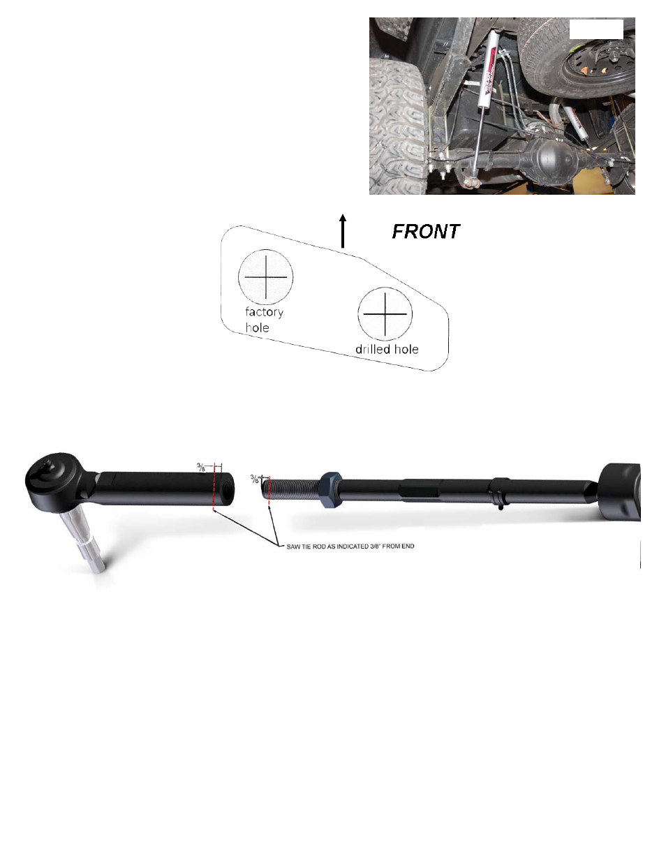
1. Disassemble the tie rod from the tie rod ends
2. Measure over 3/8” and mark.
3. Cut the tie rods / tie rod sleeves as shown below to allow the vehicle to be realigned.
4. Smooth any rough edges.
5. Reassemble the cut assembly
13. Install the supplied Rough Country 2.2 Series Performance
Shock Absorbers in the factory location with factory hardware.
Tighten using a 21mm wrench. See Photo 6. Note that these
shocks are designed to run piston down as shown.
14. Reconnect the ABS lines to the plastic retaining clip at the
bottom of each frame rail. The connector will not be reattached
to the top of the frame. Reroute the lines as needed to gain
proper slack.
15. Re-install tires and wheels.
16. Remove jack stands and lower vehicle to ground.
17. Place shock decals on shock absorbers and window decal on
vehicle.
TEMPLATE FOR SWAY BAR RELOCATION
Cut out template and position template on lower control arm as shown in Step 45.. Drill with a 11/16 drill bit and relocate the
sway bar end links into the new location.
Photo 6
POST INSTALLATION INSTRUCTIONS
1. Check all fasteners for proper torque. Check to ensure for adequate clearance between all rotating, mobile, fixed, and
heated members. Verify clearance between exhaust and brake lines, fuel lines, fuel tank, floor boards and wiring har-
ness. Check steering gear for clearance. Test and inspect brake system.
2. Perform steering sweep to ensure front brake hoses have adequate slack and do not contact any rotating, mobile or
heated members. Inspect rear brake hoses at full extension for adequate slack. Failure to perform hose check/ replace-
ment may result in component failure.
3. On some vehicles the front lower skirting will need to be trimmed if using certain wheel /tire combinations and with
heavy offset wheels. Trim only as needed.
4. Have a qualified alignment center align the vehicle immediately. Realign to factory specifications. The following are the
recommended specifications:
Caster in degrees
4.5 +-1.0
Camber in degrees
0.0—.3
Toe In in degrees
0.1 +-.2
Important note: For alignment purposes, please refer to the instructions above. The inner & outer tie rod ends may
need to be trimmed to allow the front end alignment to be set properly. Please alert your alignment specialist of
this possibility.
6. Perform head light check and adjustment to proper settings and Check and retighten wheels at 500 miles.
7. All kit components must be retightened at 500 miles and then every three thousand miles after installation. Periodically
check all hardware for tightness.
8. Install “Warning to Driver” decal on sun visor
Note: Installation of larger tires will require speedometer recalibration.
INSTRUCTIONS FOR TRIMMING TIE ROD ENDS.