Rough Country 747.20 User Manual
Page 7
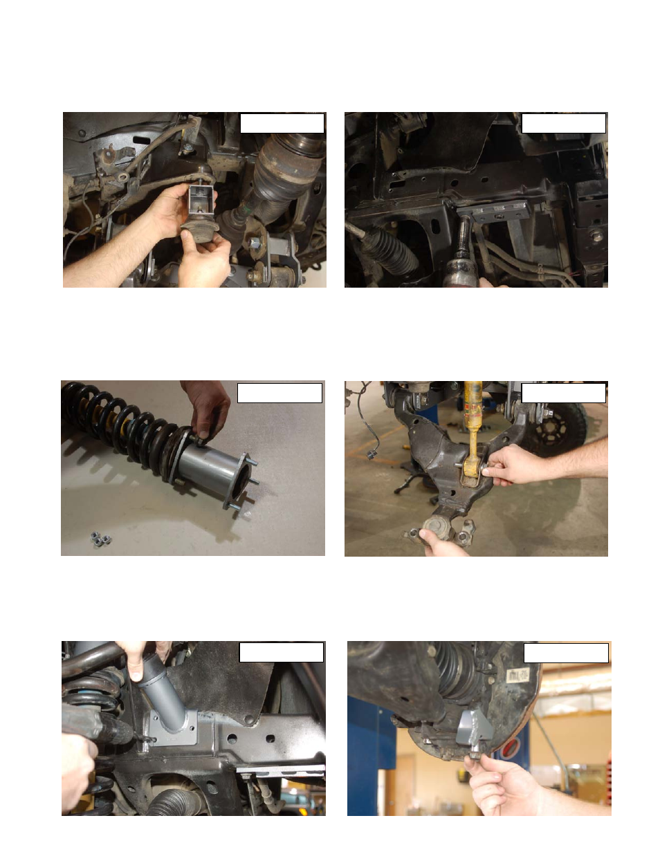
39. Using a 3” adjustable wrench, unscrew the bumpstops from the truck. Using the supplied 10mm x 35mm bolts in
1746bag2 attach the bumpstop extension to the frame. Next using the 10mm locking nuts from 1746bag2 attach the
factory bumpstop to the extension. See Photo 17. Tighten both bolts using a 17mm wrench.
40. Locate the sway bar relocation brackets and insert two of the 3/8” nuts from 1770bag4 on the back side of the
bracket. Mount to the frame using factory hardware with offset forwaed. See Photo 18. Tighten with a 14mm socket.
41. Using the supplied 3/8 stud bag, place each stud in the smaller hole end of the strut spacer facing up. Use a washer
and nut and a 9/16 socket to pull each stud into place. Slide the strut spacer over the factory strut bolts and tighten
using a 14mm wrench and factory hardware. See Photo 19.
42. Place the strut assembly into the strut tower and secure with the 3/8 nuts and washers from 1770bag4. Tighten with
a 9/16 wrench.
43. Attach the lower strut mount to the lower control arm using 19mm socket and wrench. See Photo 20.
44. Locate the supplied bump stops and bump stop brackets, screw the bump stop down tight and place the bracket on
the frame rail as shown in Photo 21. Use a 11/32” drill bit and the bump stop bracket as a drill guide and drill the
three holes in the frame. Use the self-tapping 3/8” x 1” bolts in 1770bag9 to secure bracket to the frame.
45. After sliding the steering stop bracket over the front lower ball joint bolt reinstall the new knuckle to the lower control
arm. Slide the CV shaft through the bearing hub before tightening the bolts. Tighten with a 19mm wrench. Pull down
the upper ball joint and secure with factory nut. See Photo 22.
PHOTO 17
PHOTO 18
PHOTO 22
PHOTO 21
PHOTO 19
PHOTO 20