Rough Country 480.20 User Manual
Page 2
INSTRUCTION SHEET
Technical Assistance - (731) 285-9000
Page 2
install the radius arm drop brackets.
6.
Remove the four remaining crossmember bolts just above the radius arms.
7.
Lower crossmember and install the drop brackets. Install all hardware before
tightening. Install washers against frame. Tighten four crossmember bolts
previously loosened to spread crossmember. See Figure # 1.
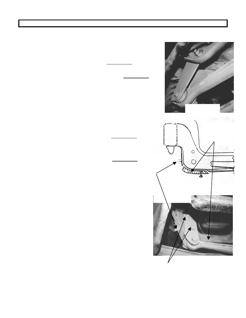
8.
Remove axle pivot bolt on passenger side of vehicle. Remove four bolts
securing axle pivot bracket to frame. Remove bracket .See Figure # 2.
9.
Replace with new axle drop bracket and secure with ½” bolts, nuts, and
washers provided in kit.
10.
Reinstall axle into pivot bracket and secure with new 9/16” bolt and nut.
11.
Remove axle pivot on driver side of vehicle.
12.
Center punch and drill out the rivets securing the rear portion of the
pivot bracket. Remove the bracket.
13.
Trim crossmember flange as shown in illustrations and picture. This
will allow for installation of new drop bracket. See Figure # 3.
14.
Install drop bracket and insert bolts. There are two spacers supplied in
the kit. The larger diameter spacer is to be used in the lower 9/16”
hole, the small diameter spacer in the upper 7/16” diameter hole. The
spacers will be on the rear of the crossmember. See Figure # 4.
15.
Be sure all bolts are installed before beginning to tighten any bolts or
nuts.
16.
Recheck all hardware for tightness.
17.
Remove stock shocks.
18.
Using a coil spring compressor, install lifted springs and secure with
stock hardware.
19.
Install new shocks, wheels and tires.
20.
Set vehicle on ground and set toe in to factory specs.
21.
Have alignments shop check front end alignment and realign if
necessary.
Be sure to leave this portion of
flange. You need this hole for
installation of drop bracket.
Trim crossmember
flange.
Drop Bracket -Drivers Side Axle
Drop Bracket -Passenger Side Axle
Figure # 2
Figure # 3
Figure # 4
Use spacers
on these bolts.
As instructed
in step # 14.