Rough Country 722.20 User Manual
Page 3
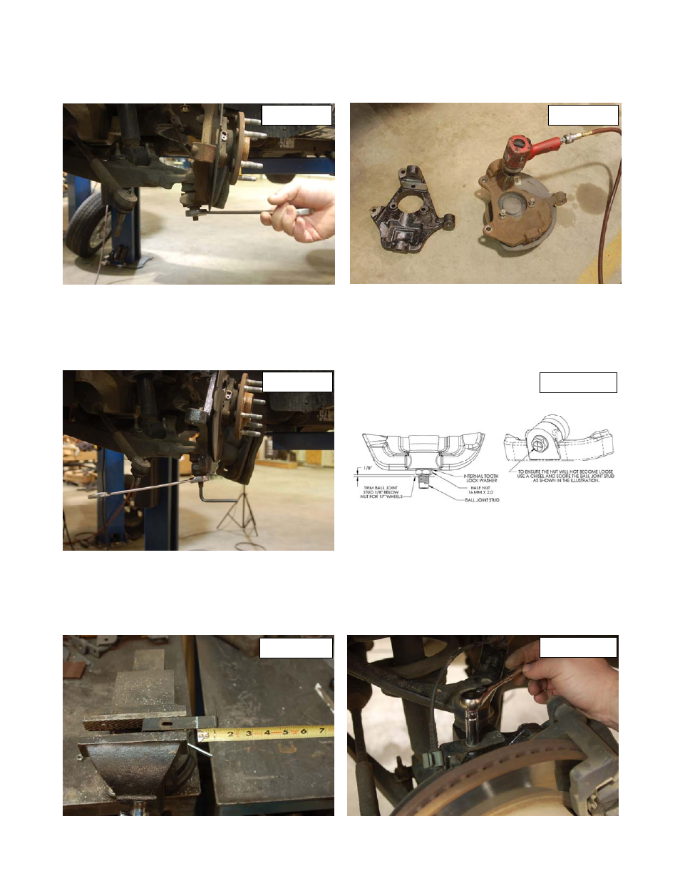
8. Remove the lower ball joint nut using a 24mm wrench, strike the side of the knuckle to dislodge the ball joint. See Photo 7. Re-
move the knuckle from the vehicle.
9. Remove the bearing assemble and dust shield from the stock knuckle using a 15mm socket. See Photo 8. Insert bearing assem-
ble and dust shield in the new Rough Country lowering knuckle and tighten.
10. Install the knuckle on the lower ball. If using a 18” wheel or bigger use the factory hardware and tighten with a 24mm wrench.
See Photo 9. Insert the upper ball joint into the knuckle with factory hardware tighten with a 18mm wrench.
11. **Note** If you using a 17” wheel with this lowering knuckle you will have to using the supplied 16mm nut and internal lock-
ing washer. Also the length of the ball stem will have to be cut off. Using a cut off blade cut the threaded stem off 1/8” below
the nut. See Photo 10.
12. Insert the tie-rod end and tighten with a 21mm wrench and install the ABS sensor in the knuckle with a 8mm allen wrench.
13. Install the brake caliper with factory hardware and tighten with a 18mm socket.
14. Place the ABS bracket in a vise and mark a line 1 1/8” from the end of the bracket. Cut the bracket so it fits on top of the new
knuckle. See Photo 11.
15. Insert the ABS wire back onto the bracket and bolt the bracket to the new knuckle using factory hardware and a 10mm socket.
See Photo 12. Repeat steps 2-13 on the passenger side.
16. Installing tires and wheels and set the truck on the ground.
PHOTO 7
PHOTO 8
PHOTO 9
PHOTO 10
PHOTO 11
PHOTO 12