Rough Country 581.20 User Manual
Page 4
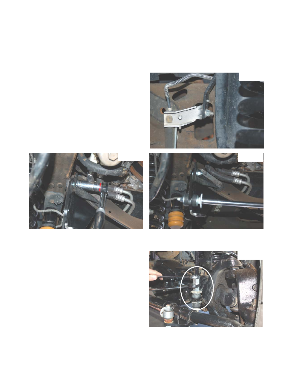
22. Factory brackets secured the brake hoses to the front of the coil spring tower on the frame, these brackets where
removed during disassembly. Remove the stock brake line strap from the brake hose to allow more of the rubber
holes to be utilized. Attach the brake line drop brackets to the coil towers where the factory brackets where mounted
using the stock hardware. Insert the supplied 5/16”x 3/4” bolt through the bracket and coil tower just below the fac-
tory bolt and secure using the supplied 5/16” nut.
23. Carefully reform the metal brake line as necessary in order to line up the factory brake hose bracket with the lower
end of the drop bracket. Attach the factory bracket to the drop bracket using the supplied 1/4” x 3/4” bolt and nut.
Attach the lower brake hose brackets to the axle using the factory hardware and tighten. See Photo 10.
24. The factory steering stabilizer bracket is attached to the front lip of the engine cross member via a two bolt tab. Re-
move the nuts securing the stabilizer mount to the cross member, using a 19mm socket. It is not necessary to en-
tirely remove the factory bracket. Position the steering sta-
bilizer drop bracket on the back side of the cross-member
lip and secure it using the factory tab bolts and nuts. Do
not tighten at this time
25. Install the supplied 5/8” X 1.50” bolt through the factory
bracket, where the stabilizer used to mount and the new
bracket. The bolt should be installed from the outside and
secured with the supplied washers and nut. Tighten the
5/8” bolt to 112 ft/lbs and the factory bolt to 136 ft/lbs. Us-
ing a 24mm socket See Photo 11.
26. Install the factory washer and bushing half on the stem end
of the stock stabilizer, them position the stem through the
remaining hole in the new stabilizer drop bracket. Install
the remaining bushing half, washer, and factory nut, then
tighten until the bushing swells slightly. See Photo 12.
27. Install tires and wheels and lower the vehicle to the ground.
28. Thread the female end of the anti-sway bar link extension and the supplied jam nut on the factory sway bar end links
and tighten to 60 ft/lbs. See Photo 13.
29. Install the track bar in the new track bar bracket. You may
have to start the truck and turn the wheels in the direction
the track bar needs to go to help align the track bar with
the hole. Tighten using the factory hardware to factory
specifications with a 30mm socket.
Photo 10
Photo 11
Photo 12
Photo 13