Bty series single channel antenn as – Toner Cable BTY-10-HB 4867 VHF Antennas User Manual
Page 2
Toner Cable Equipment, Inc.
Specifications Subject To Change Without Notice.
Telephone:
Nationwide:
Fax:
E-mail:
Internet:
BTY SERIES SINGLE CHANNEL ANTENN
AS
215-675-2053
800-523-5947
215-675-7543
http://www.tonercable.com
ORDERING INFORMATION:
BTY-LP-LB
Stock No. 4872
BTY-LP-HB
Stock No. 4871
FEATURES:
High Gain, Low Sidelobes
Foam Filled Elements
Dampen Vibration
Short Boom Reduces
Freight and Handling Costs
Cantilever Mount
Available
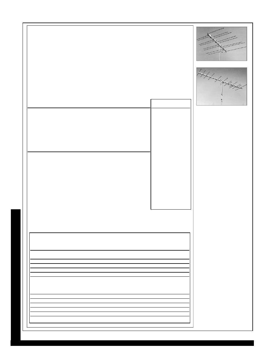
BTY-LP-LB, BTY-LP-HB
BROADBAND VHF ANTENNAS
The BTY Broadband Antenna Series includes professional quality, broadband antennas designed for
a variety of VHF applications. The BTY-LP-LB covers low band VHF channels 2-6 using 8 antenna
elements, while the BTY-LP-HB covers high band VHF channels 7-13 using 10 antenna elements.
The BTY Broadband Antennas feature high gain, narrow bandwidth, and low side lobes.
These antennas are designed with a two piece boom (assembled into one piece) allowing the anten-
nas to be shipped via UPS to reduce freight and handling costs. Square boom construction and end-
sealed aluminum elements provide added strength, excellent wind resistance and exceptional weath-
ering properties. The heavy duty mounting bracket is positioned at the antenna’s center of gravity for
balanced mounting to the mast. These antennas can be rear mounted using BTY-C-MOUNT
Cantilever Antenna Mount. This style mount permits attaching the antenna to either the horizontal or
vertical tower members. The BTY Series Antennas can accommodate a maximum mast size of 2.5”
O.D. (outside diameter). These antennas feature a 75
Ω
type “F” connector to provide feed on coax-
ial cable down leads.
SPECIFICATIONS
ELECTRICAL
BTY-LP-LB
BTY-LP-HB
Units
Gain Over Isotropic:
9.0
13.2 (ch. 7) 12.2 (ch. 13)
dBi
Bandwidth:
55-88
174-216
MHz
Flatness Over Channel:
0.25
0.50
dB
Horizontal Beamwidth:
57.0
50.5 (ch. 7) 42.0 (ch. 13)
-3 dB
VSWR:
1.50:1
1.67:1
Front to Back Ratio:
22.0
20.0
dB
Return Loss:
14.0
12.0
dB
Impedance:
75
75
Ω
MECHANICAL
Boom Length:
86.0
104.0
in
Number of Elements:
8
10
Max. Element Width:
109.13
35.50
in
Mast Mounting Bracket:
polyethylene,
stainless steel
0.375” thickness,
4.094” x 9”
Turning Radius:
68.0
64.0
in
Max. Cross Sectional Area:
1.9
1.3
sq. feet
Wind Resistance @ 100 mph:
76.2
52.0
lbs
Shipping Size (LxHxW)
87.5 x 4.0 x 5.5
73.2 x 4.5 x 5.5
in
222 x 10 x 14
186 x 11 x 14
cm
Shipping Weight:
15.40
13.25
lbs
7.00
6.02
kg
MECHANICAL
COMMON
Boom:
6063-T6 alum. tube
1.25” square, 0.062” wall
Elements:
6063-T52 alum. tube,
0.5” round, 0.049” wall
Element Mounting Clamp:
11 gauge alum. (0.090”)
Locknut Plate:
8 gauge alum. (0.125”)
Operational/Survival
Wind Velocity:
125 mph
Output Connector:
Type “F”, female,
weather sealed
Max. Mast Diameter (O.D.):
2.5”
Maximum
Wind
Element
Boom
Cross
Resistance
Antenna
Stock
Width
Length
Sectional Area
No Ice
0.5” Ice
Weight
Number
Channel
(in.)
(in.)
(sq. feet)
(lbs.)
(lbs.)
(lbs.)
BTY-5-LB
4866
2
106
128
1.56
49.84
66.16
10.20
4866
3
97
116
1.45
45.67
61.78
9.89
4866
4
85
105
1.35
41.85
56.44
9.36
4866
5
75
96
1.28
38.73
52.00
8.86
4866
6
71
96
1.20
38.73
52.00
8.61
4866
FM
64
120
1.45
47.06
63.73
9.61
BTY-10-HB
4867
7
33
131
1.48
52.56
70.27
9.61
4867
8
32
126
1.43
50.83
68.33
9.49
4867
9
32
122
1.40
49.44
66.38
9.37
4867
10
31
118
1.35
48.00
64.44
8.86
4867
11
31
115
1.33
47.00
63.00
8.99
4867
12
29
110
1.28
45.00
60.55
8.74
4867
13
28
106
1.25
43.88
58.60
8.61
BTY-5-LB, BTY-10-HB continued from front page
4871
4872