70cru02, Outline table – Vishay 70CRU02 User Manual
Page 5
Bulletin PD-20619 rev. C 12/06
70CRU02
Fig. 10 - Reverse Recovery Waveform and Defini-
tions
Fig. 9 - Reverse Recovery Parameter Test
Circuit
IRFP250
D.U.T.
L = 70µH
V = 200V
R
0.01 Ω
G
D
S
dif/dt
ADJUST
4. Q
rr
- Area under curve defined by
t
rr
and I
RRM
5. di
(rec) M
/ dt - Peak rate of change
of current during t
b
portion of t
rr
1. di
F
/dt - Rate of change of current through
zero crossing
2. I
RRM
- Peak reverse recovery current
3. t
rr
- Reverse recovery time measured from
zero crossing point of negative going I
F
to
point where a line passing through 0.75 I
RRM
and 0.50 I
RRM
extrapolated to zero current
Q
rr =
t rr x I
RRM
2
t
a
t
b
t
rr
Q
rr
I
F
I
RRM
I
RRM
0.5
di(rec)M/dt
0.75 I
RRM
5
4
3
2
0
1
di /dt
f
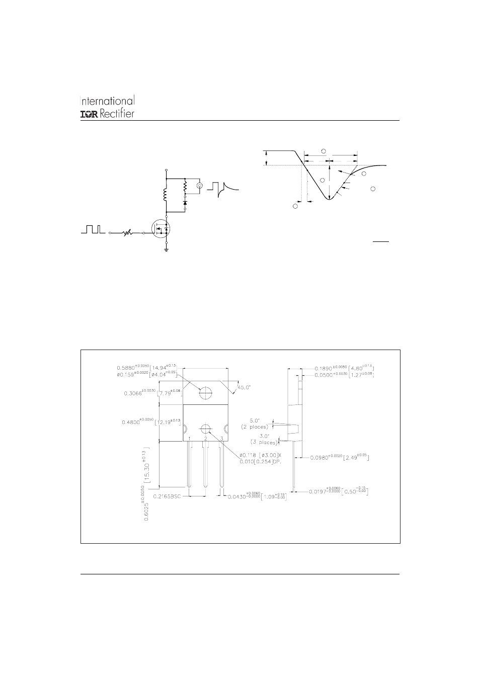
Outline Table
Dimensions in inches (and milimetres)
Document Number: 93022
www.vishay.com
5