Vishay high power products – Vishay GA200SA60UP User Manual
Page 5
Document Number: 94364
For technical questions, contact: [email protected]
www.vishay.com
Revision: 29-Apr-08
5
GA200SA60UP
Insulated Gate Bipolar Transistor
(Ultrafast Speed IGBT), 100 A
Vishay High Power Products
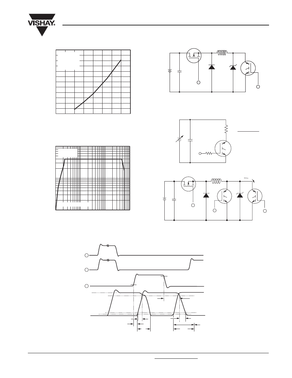
Fig. 11 - Typical Switching Losses vs. Collector Current
Fig. 12 - Turn-Off SOA
Fig. 13a - Clamped Inductive Load Test Circuit
Fig. 13b - Pulsed Collector Current Test Circuit
Fig. 14a - Switching Loss Test Circuit
Fig. 14b - Switching Loss Waveforms
Total Switching Losses (mJ)
I
C
- Collector Current (A)
0
100
200
300
400
0
10
20
30
40
50
60
R
G
= 2.0
Ω
T
J
= 150 °C
V
CC
= 480 V
V
GE
= 15 V
I
C
- Collector Current (A)
10
100
1000
1
10
100
1000
V
CE
- Collector to Emitter Voltage (V)
Safe operating area
V
GE
= 20 V
T
J
= 125 °C
D.U.T.
50 V
L
V
C
*
* Driver same type as D.U.T.; V
C
= 80 % of V
CE
(max)
Note: Due to the 50 V power supply, pulse width and inductor
will increase to obtain rated I
d
1000 V
1
2
1
2
480 V
4 x I
C
at 25 °C
480 µF
960 V
0 - 480 V
R
L
=
=
50 V
Driver*
1000 V
D.U.T.
I
C
V
C
L
* Driver same type
as D.U.T., V
C
= 480 V
3
1
2
t = 5 µs
t
d (on)
t
f
t
r
90 %
t
d (off)
10 %
90 %
10 %
5 %
V
C
I
C
E
on
E
off
E
ts
= (E
on
+ E
off
)
1
2
3