Used on ptc models, Voltage selection configuration, Back panel of enclosure – Altronix ALTV248 Series Installation Instructions User Manual
Page 4: Example: altv248cb), 24vac output, 28vac output, Terminal blocks for fig. 1, Terminal blocks for fig. 2, Yellow) (black) (black) (yellow), Xfmr
- 4 -
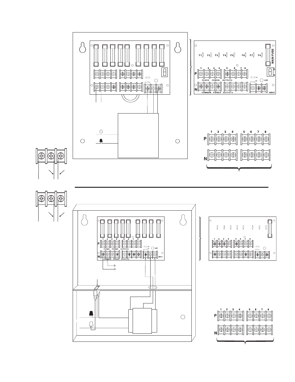
Fig. 1 - ALTV248 • ALTV248CB
XFMR
115VAC input
50/60 Hz,
White Lead
Black Lead
MA
IN FU
SE
ON
OF
F
N
COM M ON P OW ER OU TPU TS
P
FU SED POWER OU TPU TS
1 2 3 4
5 6 7 8
D1
INPUT
R1
LED
Used on PTC Models
(example: ALTV248CB)
NP
S
NP
S
24VAC or 28VAC circuit
breakered output 1
(Follow same procedure using
terminals 2P & N thru 8P & N
circuit breakered outputs 2 thru 8)
Fig. 2 - ALTV248175 • ALTV248175CB
XFMR
White Lead
Power
Switch
Black
Lead
115VAC input
50/60 Hz,
1.5 amps
24 VAC or 28VAC fused output 1
(Follow same procedure
using terminals 2P & N
thru 8P & N fused
outputs 2 thru 8)
Used on PTC Models
(example: ALTV248175CB)
N
COMMON POWE R OUTPUTS
P
FUSED POWER OUTPUTS
D1
INPUT
NP
S
R1
LED
MAIN
FUSE
MAIN
FUSE
F1
F2
F3
F4
F5
F6
F7
F8
Back Panel of Enclosure
24VAC or 28VAC fused or PTC
protected outputs 1 through 8.
Terminal Blocks for Fig. 1
24VAC or 28VAC
fused or PTC protected outputs
1 through 8.
Terminal Blocks for Fig. 2
NP
S
NP
S
24VAC
Output
(Yellow)
(Black)
(Black)
(Yellow)
28VAC
Output
Voltage Selection
Configuration