Altronix AL400UL3X Installation Instructions User Manual
Page 4
- 4 -
AL400UL3/AL400UL3X
8. It is required connect supervisory trouble reporting devices to outputs marked [AC FAIL, LOW BAT] (Fig. 1, pg. 3).
Use 22 AWG to 18 AWG for AC Fail & Low Battery reporting. AC Failure will report in 5 minutes.
Note: When used in fire alarm, burglar alarm or access control applications, “AC Fail” relay should be
utilized to visually indicate that AC power is on. To delay report 6 hours cut “AC Delay” jumper (Fig. 1b, pg. 3).
9. Please ensure that the cover is secured with the provided Key Lock.
Maintenance:
Unit should be tested at least once a year for the proper operation as follows:
Output Voltage Test: Under normal load conditions, the DC output voltage should be checked for proper voltage level
(see Terminal Identification Tables).
Battery Test: Under normal load conditions check that the battery is fully charged, check specified voltage at the
battery terminals and at the board terminals marked [+ BAT -- ] to ensure that there is no break in the battery
connection wires.
Note: Maximum charge current under discharge is 0.7 amp.
Note: Expected battery life is 5 years, however it is recommended changing batteries in 4 years or less if necessary.
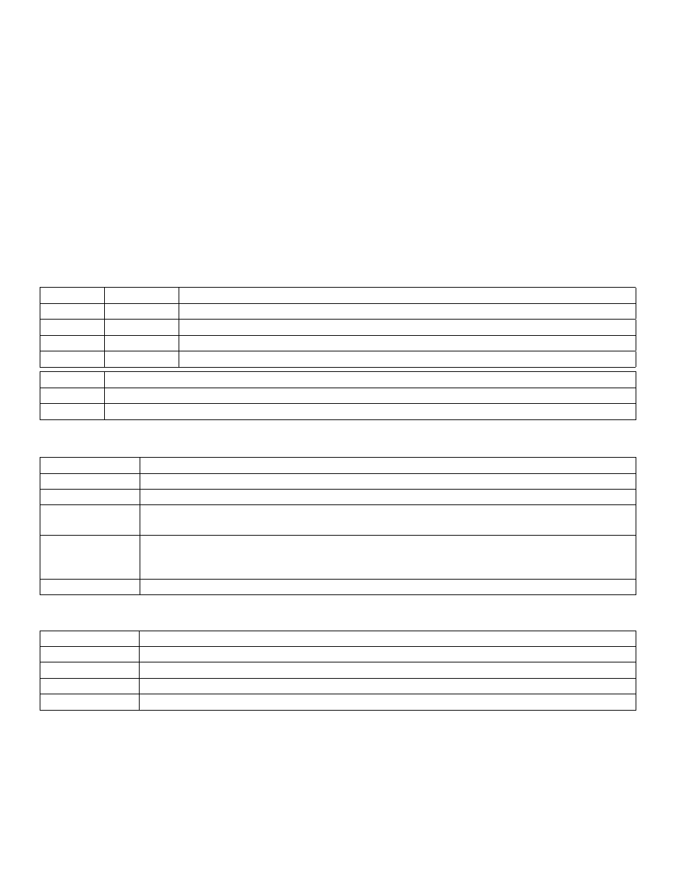
LED Diagnostics:
AL400ULXB2 - Power Supply
Red (DC)
Green (AC) Power Supply Status
ON
ON
Normal operating condition.
ON
OFF
Loss of AC, Stand-by battery supplying power.
OFF
ON
No DC output.
OFF
OFF
Loss of AC. Discharged or no stand-by battery. No Dc output.
Red (Bat)
Battery Status
ON
Normal operating condition.
OFF
Battery fail/low battery.
Terminal Identification:
AL400ULXB2 - Power Supply
Terminal Legend Function/Description
L, N
115VAC 60 Hz
+ DC –
24VDC @ 3 amp total continuous output (supplies power to ALX3B).
AC Fail
NC, C, NO
Indicates loss of AC power, e.g. connect to audible device or alarm panel. Relay normally
energized when AC power is present. Contact rating 1 amp @ 28VDC.
Bat Fail
NC, C, NO
Indicates low battery condition, e.g. no battery presence. Relay normally energized when DC power
is present. Contact rating 1 amp @ 28VDC. Low battery threshold: 24VDC output threshold is set
approximately @ 21VDC
+ BAT –
Stand-by battery connections. Maximum charge current 0.7 amp.
ALX3B - Power Output Module
Terminal Legend Function/Description
-- INPUT +
24VDC from power supply (AL400ULXB2)
+ 24VDC --
24VDC @ 1.5 amp continuous power-limited output
+ 12VDC --
12VDC @ 1.75 amp continuous power-limited output.
+ 5VDC --
5VDC @ 1.75 amp continuous power-limited output.