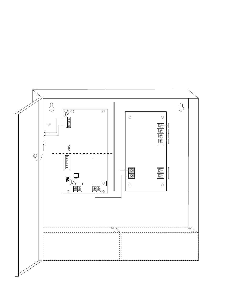
Fig. 1, Wire strap (from enclosure to door) – Altronix AL400UL3X Installation Instructions User Manual
Page 3
AL400UL3/AL400UL3X
- 3 -
2. Connect AC power (115VAC 60Hz) to the terminals marked [L, N] (Fig. 1, pg. 3). Use 18 AWG or larger for
all power connections (Battery, DC output, AC input).
Use 22 AWG to 18 AWG for power-limited circuits (AC Fail/Low Battery reporting).
Keep power-limited wiring separate from non power-limited wiring (115VAC / 60Hz Input, Battery Wires).
Minimum 0.25” spacing must be provided.
For Fire Alarm applications the outputs are “Special Applications” only, see list (refer to Appendix A, pg. 5).
3. Measure output voltage before connecting devices. This helps avoiding potential damage.
4. Connect devices to be powered at 5VDC to the terminals marked [+ 5VDC -- ].
5. Connect devices to be powered at 12VDC to the terminals marked [+ 12VDC -- ].
6. Connect devices to be powered at 24VDC to the terminals marked [+ 24VDC -- ].
7. Connect two (2) 12V Stand-by batteries.
Note: For Access Control applications batteries are optional. When batteries are not used, a loss of AC will result in
the loss of output voltage. Batteries must be lead acid or gel type if used. Two (2) 12V Stand-by batteries
connected in series to the terminals marked [+ BAT -- ] (Fig. 1 , pg. 3).
+
DC ---
NC C NO NC C NO
+
BAT ---
AC
DC
Ba
t
Risk of Fi
re
,
Replace Fuse
s
As Marked
Opened - 24V
Closed - 12
V
AC Fail
Bat Fail
J1
SW
1
5A 250V
15A 250V
AC Delay
15
L
G
N
115VAC
power mains
non power-
limited
Class 1
Battery 1
Battery 2
Battery connection
(non power-limited)
Outputs to
devices are
power-limited
Wire Strap
(from
Enclosure
to Door)
+ 12VDC
---
+ 5VDC
---
+ 24VDC
---
+ INPUT1
---
24VDC
12VDC
5VDC
CAUTION: De-energize unit prior to servicing. For continued protection against risk of electric shock and fire hazard
replace fuse with the same type and rating. Do not expose to rain or moisture.
Earth
Ground
Fig. 1