Addressable control module trigger output, Optional hookup diagram, Fig. 2 – Altronix AL842ULADA Installation Instructions User Manual
Page 7: Fig. 2b fig. 2a, Green lead, Wire smoke detector, Magnetic door holder
AL842ULADA
- 7 -
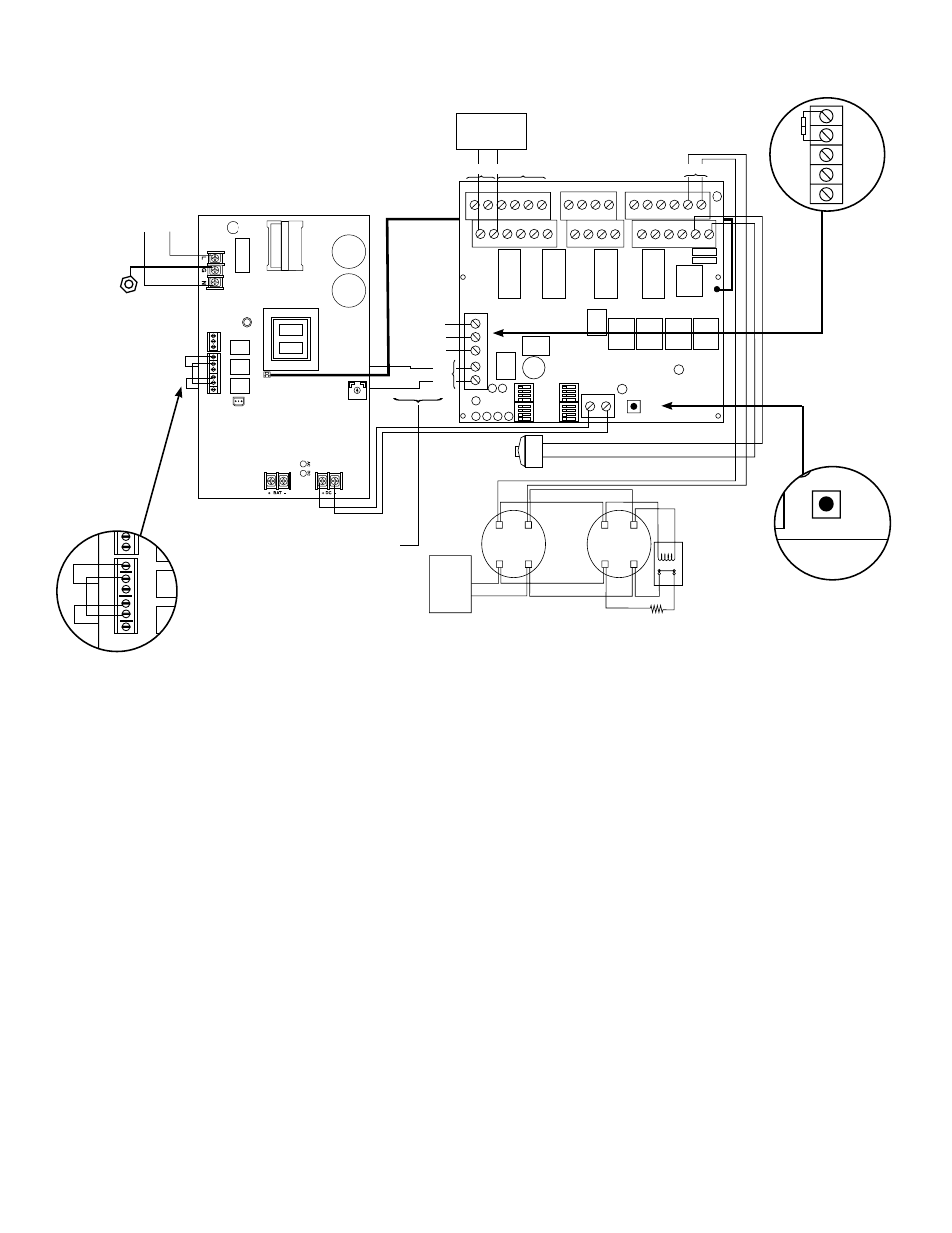
Fig. 2
Optional Hookup Diagram:
Fig. 2b
Fig. 2a
NC
NO
C
NC
C NO
NC
C
NO
AC Loca
l
AC DELAY
BA
T F
AIL
AC
FA
IL
AC LE
D
VR
1
OUT1 OUT2 OUT3 OUT4
INP2 INP1
FAULT
RESET
OUT1
OUT3
OUT2
OUT4
IN>OUT SYNC
STROBE SYNC
TEMPORAL
INPUT SELECT
IN>OUT SYNC
STROBE SYNC
TEMPORAL
INPUT SELECT
NC C NO C "F
AUL
T" NC
+ DC ---
-- AUX2 +
-- LOOP4 +
-- OUT4 +
-- OUT3 +
-- LOOP3 +
-- LOOP1 +
-- OUT1 +
-- OUT2 +
-- LOOP2 +
-- IN1 +
-- RET1 +
-- IN2 +
-- RET2 +
NC "DRY1" C
NC "DRY2" C
-- AUX1 +
Green Lead
Addressable
control module
trigger output
(See Typical Application Diagram for device hookup)
Power-Limited Outputs 2.5 amp per output max.
(total = 8 amp)
(Supervised)
+ --
4-wire Smoke
Detector
+ --
4-wire Smoke
Detector
Fire
Alarm
Control
Panel
(FACP)
EOL Power
Supervision Relay
(Not Supplied)
EOL Resistor
from FACP
Digital Communicator or Local
Annunciator Dr
y
output Contact
(Form "C" contacts)
These circuits are used
to monitor AC and Bat Fail
and will cause
a simultaneous
trouble condition to the
FACP's IN1 and IN2
(Non-Supervised)
Factory Installed
Board Interface
Cable
AC
Magnetic
Door Holder
line
ground
neutral
unswitched 120VAC
power mains
(non-power limited)
Supervised
Non-Supervised
Non-Supervised
Non-
Super
vised
NC
NO
C
NC
C NO
NC
C
NO
AC Loca
l
AC DELAY
BA
T F
AIL
AC
FA
IL
AC LE
D
VR
1
OUT1 OUT2 OUT3 OUT4
INP2 INP1
FAULT
RESET
OUT1
OUT3
OUT2
OUT4
IN>OUT SYNC
STROBE SYNC
TEMPORAL
INPUT SELECT
IN>OUT SYNC
STROBE SYNC
TEMPORAL
INPUT SELECT
NC C NO C "F
AUL
T" NC
+ DC ---
-- AUX2 +
-- LOOP4 +
-- OUT4 +
-- OUT3 +
-- LOOP3 +
-- LOOP1 +
-- OUT1 +
-- OUT2 +
-- LOOP2 +
-- IN1 +
-- RET1 +
-- IN2 +
-- RET2 +
NC "DRY1" C
NC "DRY2" C
-- AUX1 +
Green Lead
Addressable
control module
trigger output
(See Typical Application Diagram for device hookup)
Power-Limited Outputs 2.5 amp per output max.
(total = 8 amp)
(Supervised)
+ --
4-wire Smoke
Detector
+ --
4-wire Smoke
Detector
Fire
Alarm
Control
Panel
(FACP)
EOL Power
Supervision Relay
(Not Supplied)
EOL Resistor
from FACP
Digital Communicator or Local
Annunciator Dr
y
output Contact
(Form "C" contacts)
These circuits are used
to monitor AC and Bat Fail
and will cause
a simultaneous
trouble condition to the
FACP's IN1 and IN2
(Non-Supervised)
Factory Installed
Board Interface
Cable
AC
Magnetic
Door Holder
line
ground
neutral
unswitched 120VAC
power mains
(non-power limited)
Supervised
Non-Supervised
Non-Supervised
Non-
Super
vised
NC
C
NO
C "F
AUL
T" NC
Fig. 2c
Trouble Memory
Reset Button
+ DC
---
BA
T
FA
IL
NO C NC NO C NC
+ BA
T
---
L
G
N
DC
AC
FA
IL
AC
15A
32V
10A
250V
OUT1 OUT2 OUT3 OUT4
INP2 INP1
FAULT
RESET
OUT1
OUT3
OUT2
OUT4
IN>OUT SYNC
STROBE SYNC
TEMPORAL
INPUT SELECT
IN>OUT SYNC
STROBE SYNC
TEMPORAL
INPUT SELECT
NC C NO C "F
AUL
T" NC
+ DC ---
-- AUX2 +
-- LOOP4 +
-- OUT4 +
-- OUT3 +
-- LOOP3 +
-- LOOP1 +
-- OUT1 +
-- OUT2 +
-- LOOP2 +
-- IN1 +
-- RET1 +
-- IN2 +
-- RET2 +
NC "DRY1" C
NC "DRY2" C
-- AUX1 +
Green Lead
Addressable
control module
trigger output
(See Typical Application Diagram for device hookup)
Power-Limited Outputs 2.5 amp per output max.
(total = 10 amp)
+ --
4-wire Smoke
Detector
+ --
4-wire Smoke
Detector
Fire
Alarm
Control
Panel
(FACP)
EOL Power
Supervision Relay
(Not Supplied)
EOL Resistor
from FACP
Digital Communicator or
Local
Annunciator Dr
y
output Contact
(Form "C" contacts)
These circuits are used to monitor
AC and Bat Fail and will cause a
simultaneous trouble condition
to the FACP's IN1 and IN2
(Non-Supervised)
Factory Installed
Board Interface
Cable
AC
Fuse
Cover
unswitched 115VAC
50/60Hz, 4.4 amp
power mains
(non power-limited)
Magnetic
Door Holder