Wire strap (from enclosure to door) – Altronix AL600UL3 Installation Instructions User Manual
Page 3
AL600UL3/AL600UL3X
- 3 -
4. Connect 5VDC devices to be powered at 5VDC to the terminals marked [+ 5VDC -- ].
5. Connect 12VDC devices to be powered at 12VDC to the terminals marked [+ 12VDC -- ].
6. Connect 24VDC devices to be powered at 24VDC to the terminals marked [+ 24VDC -- ].
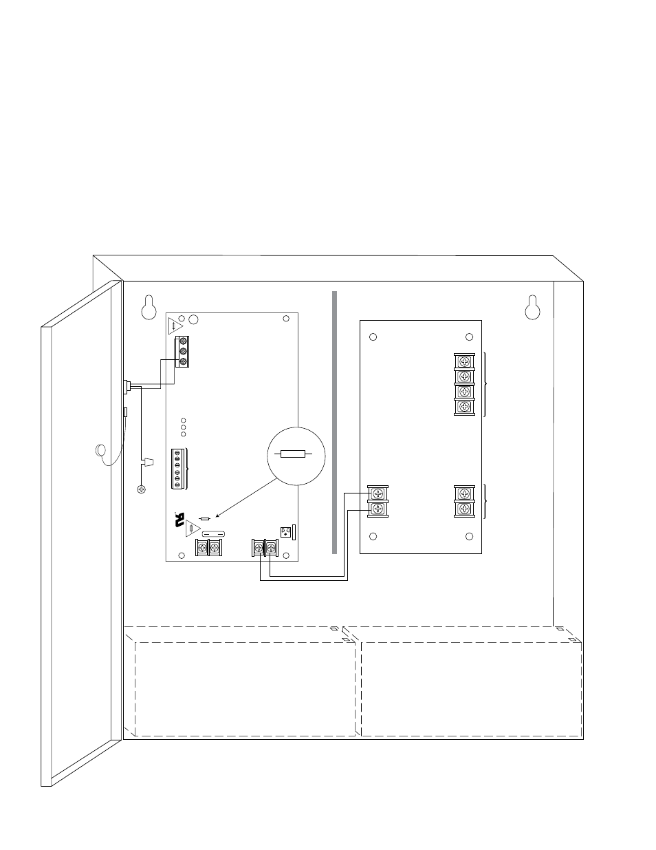
7. Connect two (2) 12V Stand-by batteries.
Note: For Access Control applications batteries are optional. When batteries are not used a loss of AC will result in
the loss of output voltage. Batteries must be lead acid or gel type if used. Two (2) 12V Stand-by batteries
connected in series to terminals marked [+ BAT -- ] (Fig. 1 , pg. 3).
8. It is required connect supervisory trouble reporting devices to outputs marked [AC FAIL, LOW BAT] (Fig. 1, pg. 3).
Use 22 AWG to 18 AWG for AC Fail & Low Battery reporting. AC Failure will report in 5 minutes.
Note: When used in fire alarm or access control applications, “AC Fail” relay should be utilized to visually indicate
that AC power is on. To delay report 6 hours cut “AC Delay” jumper (Fig. 1a, pg. 3).
9. Please insure that the cover is secured with the provided Key Lock.
Fig. 1
+
DC ---
NC C NO NC C NO
+
BAT ---
AC
DC
Ba
t
Risk of Fire
,
Replace Fuses
As Marked
Opened - 24V
Closed - 12V
AC Fail
Bat Fail
J1
SW
1
5A 250V
15A 250V
AC Delay
15
L
G
N
Wire Strap
(from
Enclosure
to Door)
+ 12VDC
---
+ 5VDC
---
+ 24VDC
---
+ INPUT1
---
CAUTION: De-energize unit prior to servicing. For continued protection against risk of electric shock and fire hazard
replace fuse with the same type and rating. Do not expose to rain or moisture.
24VDC output
is non
power-limited
5VDC and
12VDC outputs
are power-limited
Battery
connection
(non power-limited)
(non power-limited)
(non
power-
limited)
Earth
Ground
CAUTION: Optional rechargeable stand-by batteries must match the power supply
output voltage setting.
Keep power-limited wiring separate from non power-limited. Use minimum 0.25" spacing.
Optional Rechargeable
Stand-by Battery
Optional Rechargeable
Stand-by Battery
Battery and
AC Supervision
Circuit
(power-limited)
J1
AC Delay
Fig. 1a