Altronix SMP10PMC24X Installation Instructions User Manual
Page 2
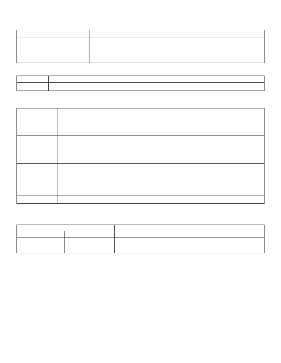
LED Diagnostics:
OLS250/OLS257 - Power Supply Board
Red (DC)
Green (AC)
Power Supply Status
ON
ON
Normal operating condition
ON
OFF
Loss of AC, Stand-by battery supplying power
OFF
ON
No DC output
OFF
OFF
Loss of AC. Discharged or no stand-by battery. No DC output.
PD4/PD4CB/PD8/PD8CB - Power Distribution Module
Green
Power Distribution Module Status
ON
Normal operating condition.
Terminal Identification:
OLS250/OLS257 - Power Supply Board
Terminal
Function/Description
Legend
L, G, N
Connect 115VAC to these terminals:
L to Hot, N to Neutral, G to ground (if used).
+ DC -
24VDC @ 10 amp continuous outputs.
*AC FAIL
Used to notify loss of AC power, e.g. connect to audible device or alarm
N.O., C, N.C.
panel. Relay normally energized when AC power is present.
Contact rating 1 amp @ 120VAC / 28VDC
*Low Battery
Used to indicate low battery condition, e.g. connect to alarm panel.
N.O., C, N.C.
Relay normally energized when DC power is present.
Contact rating 1 amp @ 120VAC / 28VDC
Low battery threshold:
24VDC output threshold set @ approximately 21VDC.
- BAT +
Stand-by battery connections. Maximum charge rate .7 amp.
*Note: Supervised Models Only.
PD4/PD4CB/PD8/PD8CB - Power Distribution Module
Terminal Legend
Function/
PD4/PD4CB
PD8/PD8CB
Description
1P to 4P
1P to 8P
Positive DC power outputs.
1N to 4N
1N to 8N
Negative DC power outputs.
- 2 -