Altronix SMP10PMC24X Installation Instructions User Manual
Smp1024x series
Installation Instructions:
The units should be installed in accordance with The National Electrical Code and all applicable Local Regulations.
1. Mount the unit in desired location.
2. Connect AC power to terminals marked [L & N], connect ground to terminal marked [G] (if used).
Use 18 AWG or larger for all power connections (Battery, DC output).
3. Measure output voltage before connecting devices. This helps avoid potential damage.
4. Connect devices to be powered:
a. For Power Supply Board connect to terminals marked [+ DC -].
b. For Power Distribution Module(s) connect devices to be powered to terminal pairs 1 to 4 marked
[1P & 1N thru 4P & 4N] (Fig. 2, pg. 3) or 1 to 8 marked [1P & 1N thru 8P & 8N] (Fig. 3, pg. 3) carefully
observing correct polarity.
5. When using stand-by batteries, they must be lead acid or gel type. Connect battery to terminals marked [- BAT +]
(battery leads included).
Note: When batteries are not used a loss of AC will result in the loss of output voltage.
6. For Supervised Models Only.
Connect appropriate signaling notification devices to AC Fail & Low Bat supervisory relay outputs marked
[N0 C, NC] (Fig. 1A, pg. 3).
SMP10C24X
-
1
-
-
10
-
2.7
10
SMP10PMC24X
-
1
-
-
10
x
2.7
10
SMP10PM24P4
PD4
4
x
-
3.5
x
2.7
10
SMP10PM24P4CB
PD4
4
-
x
2.5
x
2.7
10
SMP10PM24P8
PD8
8
x
-
3.5
x
2.7
10
SMP10PM24P8CB
PD8
8
-
x
2.5
x
2.7
10
SMP10PM24P16
PD8
16
x
-
3.5
x
2.7
10
SMP10PM24P16CB
PD8
16
-
x
2.5
x
2.7
10
Altronix
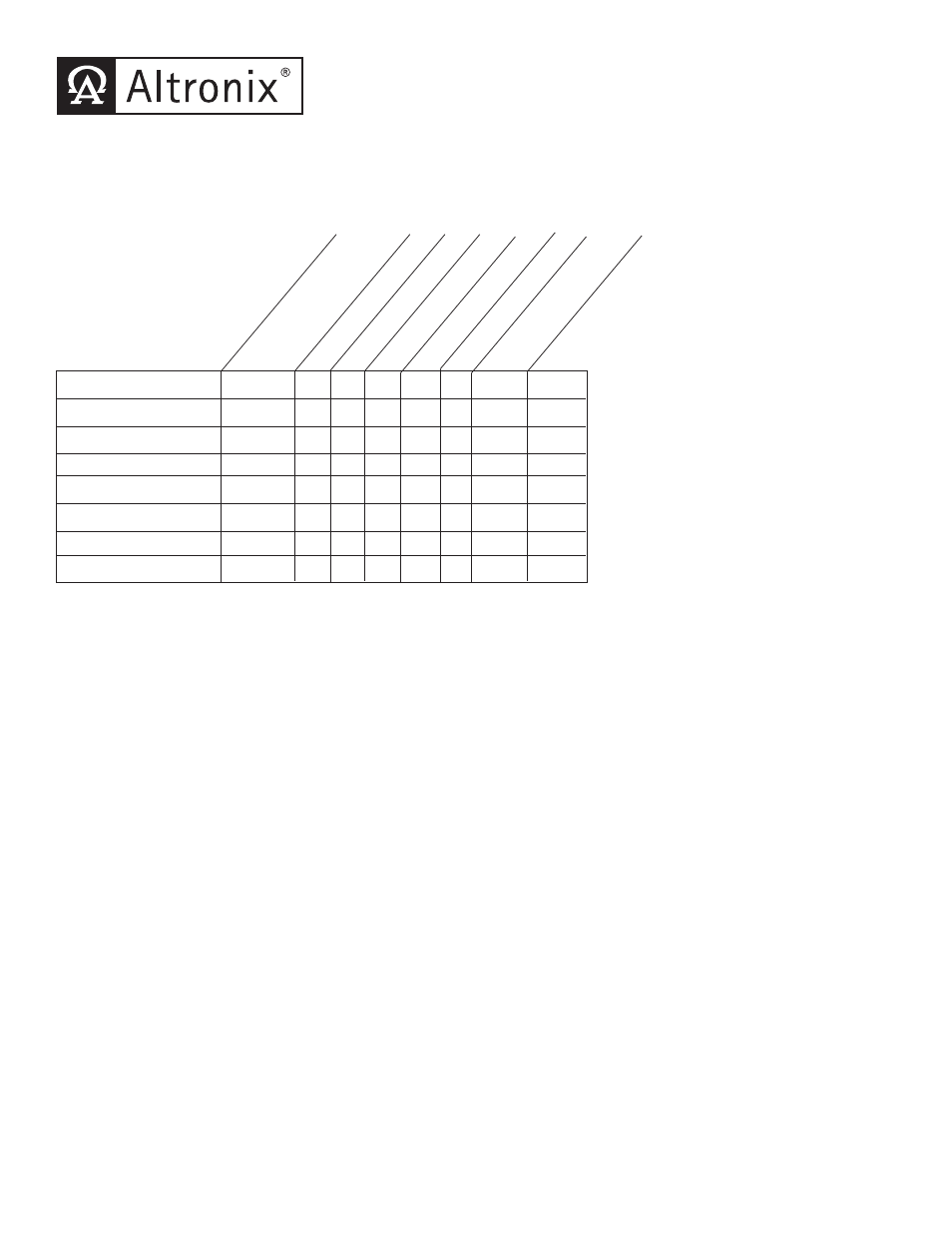
Model Number
Accessor
y P
ow
er
Distribution
Module(s)
Number of Outputs
Fused Outputs
PTC Outputs
Output Rating (amp)
115V
AC / 60Hz
Input Current (amp)
24VDC T
otal
Output
Current (amp)
SMP1024X Series Power Supply Configuration Reference Chart:
Overview:
These units will convert a 115VAC / 60Hz input, into a regulated 24VDC output at up to 10 amps of continuous supply
current (see specifications).
• Maximum charge current .7 amp.
• Filtered and electronically regulated outputs.
• Built-in charger for sealed lead acid or gel type batteries.
• Automatic switch over to stand-by battery when
AC fails (zero voltage drop).
• AC input and DC output LED indicators.
• Short circuit and thermal overload protection.
• Complete with power supply, power distribution module
(when applicable), enclosure, cam lock & battery leads.
Supervised models only:
• AC fail supervision (form "C" contacts).
• Low battery supervision (form "C" contacts).
- 1 -
SMP1024X Series
Supervised
Specifications: