Netway1 – Altronix NetWay1 Installation Instructions User Manual
Page 2
- 2 -
NetWay1
Installing a NetWay1512 adapter for 12VDC IP cameras up to 13W:
1. Mount NetWay1512 in proximity of IP camera (Fig. 3, pg. 3). Use velcro (supplied).
2. Connect structured cable from port marked [IN] on NetWay1512 to port marked [OUT] of NetWay1
(Fig. 3, pg. 3, Fig. 1b pg. 2).
3. Connect structured cable from port marked [OUT] on NetWay1512 to the IP camera/device (Fig. 3, pg. 3, Fig. 1b pg. 2).
4. Connect 12VDC output from NetWay1512 terminals marked [+ 12VDC --- ] to the power input of the
IP camera (Fig. 3, pg. 3). Polarity must be observed.
5. Power LED indicator will illuminate on NetWay1512 under normal conditions (Fig. 3, pg. 3).
NetWay1 Port Status and LED Flash Codes
Port Status
Flash Code
Flash Pattern
Non-Powered Device 0
Ω <
R
PORT < 200
Ω
OFF
LED OFF
Port Open
R
PORT > 1M
Ω
OFF
LED OFF
Port On 25k
Ω
ON
LED ON
Low Signature Resistance 300
Ω <
R
PORT < 15k
Ω
1 Flash
Z
l l l
Z
l l l
Z
l l l
High Signature Resistance 33K
Ω <
R
PORT < 500k
Ω
2 Flashes
Z Z
l l
Z Z
l l
Z Z
l l
Port Overload Fault
5 Flashes
l l l l
Z Z
Z Z Z
l l l l
Installing NetWayXT repeater module:
1. Mount NetWayXT in desired location utilizing the mounting hole (Fig. 4, pg. 3). Use a proper fastener and/or wall
anchor when securing NetWayXT to the wall.
2. Connect structured cable from port marked [OUT] on NetWay1 to port marked [IN] on the
NetWayXT (Fig. 4, pg. 3, Fig. 1b pg. 2).
3. Connect structured cable from port marked [OUT] on NetWayXT to the PoE camera/device or next NetWayXT
repeater
(Fig. 4, pg. 3).
4. Port status LEDs will illuminate on NetWayXT indicating the port is operational (Fig. 4, pg. 3,
refer to Port LED definitions on pg. 2).
Port LED definitions for NetWayXT repeater:
Status
Green LED
Yellow LED
OFF
Indicates it is connected as 10Base-T or no link.
Indicates no link.
ON
Indicates it is connected as 100Base-T.
Indicates a link.
Blinking
-------
Indicates activity.
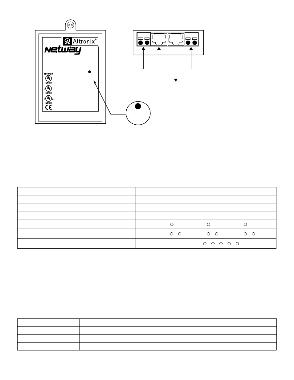
Structured
Cable from
Network
Switch
24VAC/
24VDC Input
12VAC to 24VAC or
5VDC to 24VDC Input
for PoE shutdown
Structured Cable from
IP Camera, IP Lock or IP device,
NetWay1512 or NetWayXT
24VAC/VDC
Input
Power
Shutdown
IN
OUT
Port
Status
General Signaling
Equipment 92R2
I.T.E. 43KC
NetWay1
Single Port Injector (Midspan)
24VAC/VDC, 1.2A Input
48VDC 15.4W max. per IEEE 802.3af
www.altronix.com
Equipment 92R2
Access Control PoE Injector
Attack Class
I
Fig. 1b
Fig. 1a
Structured
Cable from
Network
Switch
24VAC/
24VDC Input
12VAC to 24VAC or
5VDC to 24VDC Input
for PoE shutdown
Structured Cable from
IP Camera, IP Lock or IP device,
NetWay1512 or NetWayXT
24VAC/VDC
Input
Power
Shutdown
IN
OUT
Port
Status
General Signaling
Equipment 92R2
I.T.E. 43KC
NetWay1
Single Port Injector (Midspan)
24VAC/VDC, 1.2A Input
48VDC 15.4W max. per IEEE 802.3af
www.altronix.com
Equipment 92R2
Access Control PoE Injector
Attack Class
I
Fig. 1c
Fig. 1