Technical specifications – Altronix eBridge1CRT Installation Instructions User Manual
Page 2
- 2 -
eBridge1CRT
c. Connect structured cable from ethernet switch/NVR (network video server) to RJ45 jack marked [10/100BaseT]
(Fig. 2, pg. 3).
d. Connect Coax cable to BNC connector marked [Coax] (Fig. 2, pg. 3).
e. For optional simultaneous Composite Video transmission, attach the Composite Video Cable (Fig. 2, pg. 3) by
plugging the two (2) position connector into the Comp. Video input marked on the unit
(
Note: connector is polarized). Connect the BNC side to the composite video input of the NVR,
monitor display, matrix switch or other headend equipment.
2.
eBridge1CT installation:
a. Secure unit to desired mounting surface with a proper fastening device utilizing the case’s mounting hole
(Fig. 2a, pg. 3). Unit should be mounted in proximity of camera/device.
b. Connect 16VAC/24VAC Class 2 plug-in transformer or 12VDC/24VDC (polarity not observed) Class 2 power
supply to jack marked [Power Input] utilizing barrel connector (supplied) (Fig. 2, pg. 3).
Use 22AWG-16AWG wire for this connection.
c. Connect structured cable from IP camera/device to RJ45 jack marked [10/100BaseT] (Fig. 2, pg. 3).
d. Connect Coax cable to BNC connector marked [Coax] (Fig. 2, pg. 3).
e. For simultaneous optional Composite Video transmission, attach the Composite Video Cable (Fig. 2, pg. 3) by
plugging the two (2) position connector into the Comp. Video input marked on the unit
(
Note: connector is polarized). Connect the BNC side to the composite video output of the camera.
Note: The eBridge is designed to accommodate Megapixel, HD720, HD1080 and VGA (SD) cameras. It is important
to note that some high resolution and high frame rate cameras may demand faster headend processing ability, such as a
PC graphics card to present a quality image. If the headend processing equipment is insufficient in speed, the image may
show pixilation and latency. It is advisable to pretest system if unsure. Alternatively, frame rate and resolution may be
reduced to accommodate system equipment.
Technical Specifications:
Parameter
Description
Connections
BNC for Coax link. RJ45 for ethernet link.
Composite video connector for optional composite video service
Input power requirements 12VDC/275mA, 24VDC/110mA, 16VAC/375mA, 24VAC/200mA
Indicators
Blue: Coax Link.
Yellow (RJ45 connector): On - Link, Off - No Link, Blinking - Activity.
Green (RJ45 connector): On - 100Base-TX, Off - 10Base-T.
Green: Power.
Environmental
Conditions
Operating Ambient Temperature: UL60950-1 14ºF to 122ºF (-10ºC to 50ºC).
Relative humidity: 85%, +/ --- 5%
Storage Temperature: --- 4º to 158ºF (--- 20º to 70ºC) Storage
Operating Altitude: --- 1000 to 6,561.679 ft. (--- 304.8 to 2000m).
Regulatory Compliance
UL/CUL Listed for Information Technology Equipment (UL 60950-1). CE approved
Weights (approx.)
Product: 4 oz. (0.11 kg.), Shipping: 7 oz. (0.17 kg.)
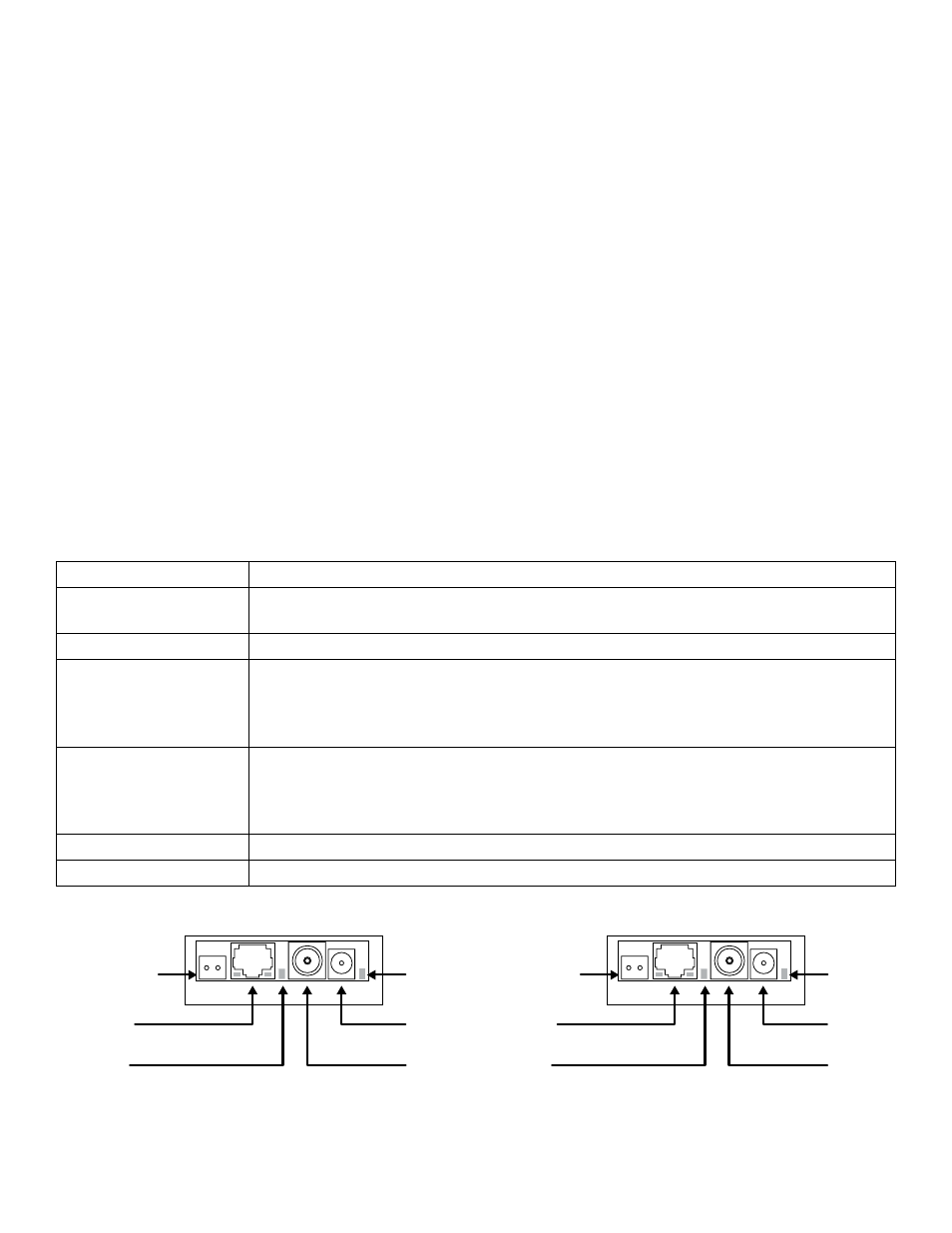
Fig. 1
eBridge1CR
eBridge1CT
Optional
Composite
Video Connector
to Camera
Green LED
indicates
Power
Structured
Cable from
Ethernet Switch/NVR
Structured
Cable from
IP Camera/Device
Optional
Composite
Video Connector
to Monitor
Blue LED
indicates
Coax Connection
Blue LED
indicates
Coax Connection
Green LED
indicates
Power
12 to 24
VAC or VDC
Input
Coax
Cable from
eBridge1CT
12 to 24
VAC or VDC
Input
Coax
Cable from
eBridge1CR