Fig. 2 fig. 3, Power distribution module(s): led diagnostics, Fig. 4 – Altronix SMP7PMP8CB Installation Instructions User Manual
Page 3: Red (dc) green (ac) power supply status
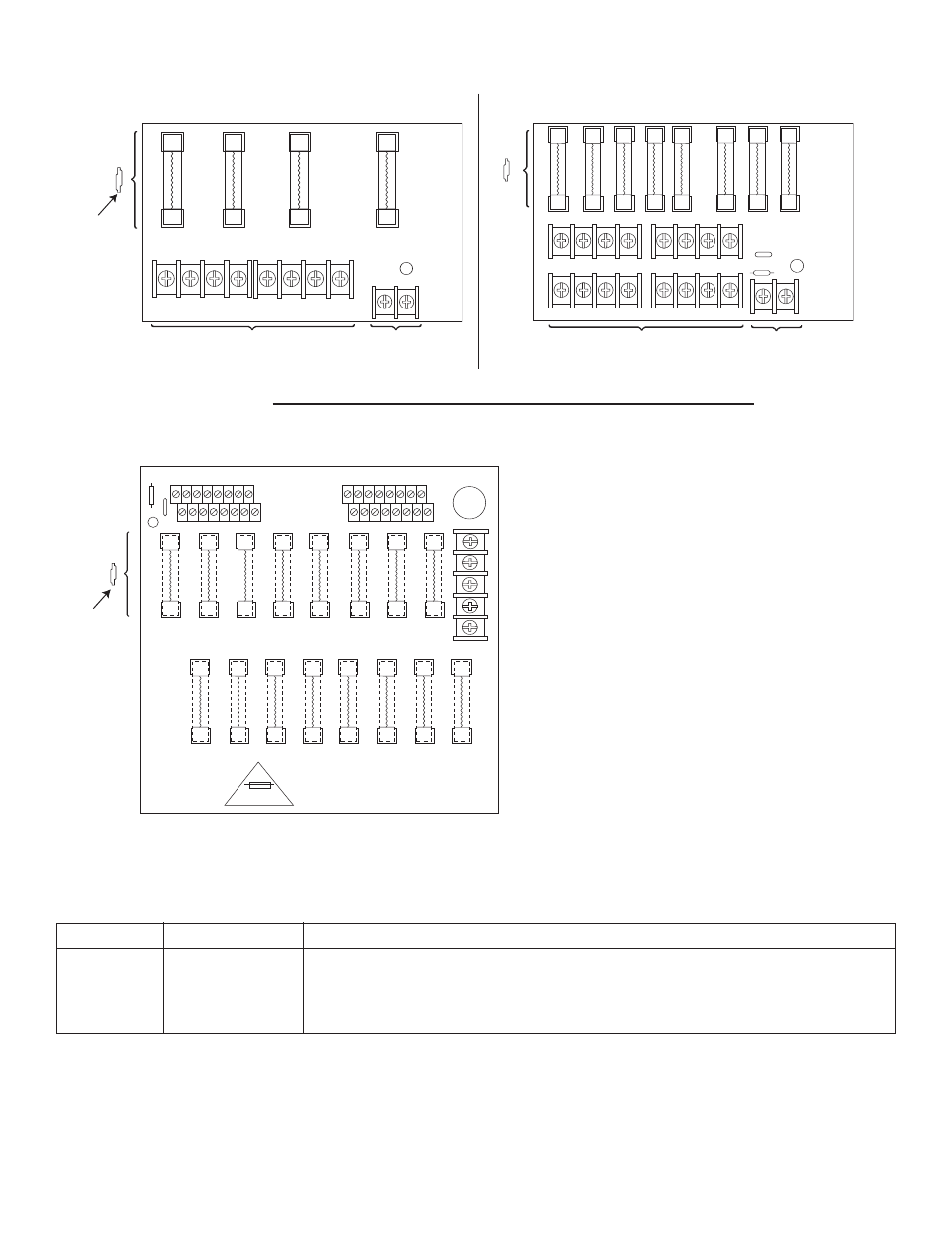
INPUT
LED
1P, 2P, 3P, 4P = FUSED OUTPUTS
1N, 2N, 3N, 4N = COMMON OUTPUTS
F1
F1
F2
F3
F4
COMMON POWER OUTPUTS
1P
1N
2P
2N
3P
3N
4P
4N
DC Output to devices
From Power Supply
Board
(Factory Installed)
Used on
PTC Models
N
COMMON POWER OUTPUTS
P
FUSED POWER OUTPUTS
1 2 3 4
5 6 7 8
1
D1
INPUT
R1
LED
DC Output to devices
From Power Supply
Board
(Factory Installed)
Fig. 2
Fig. 3
- 3 -
Power Distribution Module(s):
LED Diagnostics:
Red (DC)
Green (AC)
Power Supply Status
ON
ON
Normal operating condition.
ON
OFF
Loss of AC, Stand-by battery supplying power.
OFF
ON
No DC output.
OFF
OFF
Loss of AC. Discharged or no stand-by battery. No DC output.
common
outputs
protected
outputs
P
N
N
P
S
XFMR Input
12345678
9 10 11 12 13 14 15 16
P
N
3.5A 250V
For continuous protection against risk of fire
replace fuses with same type and rating.
Used on
PTC Models
Fig. 4
- NetWay3012 Installation Instructions (2 pages)
- HubWay 16Di Data Sheet (2 pages)
- Maximal77 Installation Instructions (20 pages)
- HubWay Dvi Data Sheet (1 page)
- HubWay Av2 Data Sheet (1 page)
- PD4CB Installation Instructions (1 page)
- ACM4CB Data Sheet (2 pages)
- VertiLine63D Data Sheet (2 pages)
- eBridge16CR Installation Instructions (8 pages)
- LPS3WP12 Data Sheet (2 pages)
- VertiLine246D Data Sheet (2 pages)
- T24130D Data Sheet (1 page)
- eBridge1PCRTX Data Sheet (2 pages)
- RB5 Installation Instructions (1 page)
- Tempo2 Data Sheet (1 page)
- BC600G Data Sheet (1 page)
- eBridge1CRT Data Sheet (2 pages)
- AL400ULB Data Sheet (1 page)
- PT2724 Installation Instructions (8 pages)
- OLS180 Installation Instructions (2 pages)
- HubWay 8CD Data Sheet (2 pages)
- AL175ULB Data Sheet (1 page)
- StrikeIt2 Installation Instructions (8 pages)
- LPD Data Sheet (1 page)
- eBridge4SK Installation Instructions (8 pages)
- LPS3AC Installation Instructions (2 pages)
- T2428100 Data Sheet (1 page)
- TP1650 Data Sheet (1 page)
- T2885D Data Sheet (1 page)
- T2428175 Installation Instructions (1 page)
- T1656 Installation Instructions (1 page)
- SMP3 Data Sheet (1 page)
- RBR1224 Data Sheet (1 page)
- HubWay LD16D Data Sheet (2 pages)
- eFlow102NX16D Installation Instructions (16 pages)
- T24175C Data Sheet (1 page)
- Maximal5D Data Sheet (2 pages)
- Maximal7 Installation Instructions (16 pages)
- HubWay 8CDS Data Sheet (2 pages)
- eFlow4NX8D Installation Instructions (16 pages)
- MOM5C Data Sheet (1 page)
- eBridge16PCRX Installation Instructions (8 pages)
- HubWay EX16SP Data Sheet (2 pages)
- T24130C Installation Instructions (1 page)
- Maximal5 Data Sheet (2 pages)