Fig. 1 fig. 1a fig. 1b, Power supply board power distribution module(s) – Altronix SMP7PMP8CB Installation Instructions User Manual
Page 2
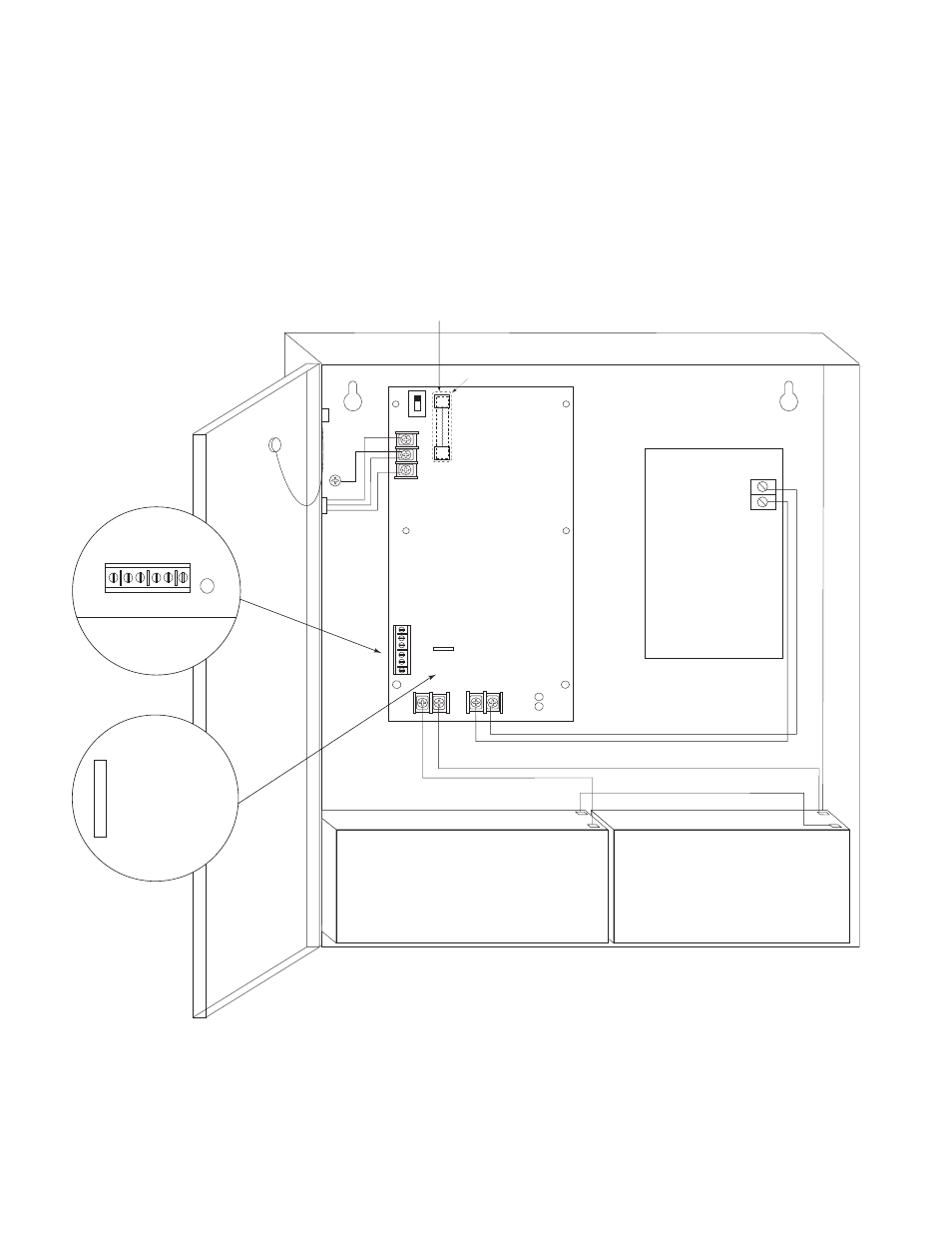
[1P & 1N through 4P & 4N] (Fig. 2, pg. 3), 1 to 8 marked [1P & 1N through 8P & 8N] (Fig. 3, pg. 3)
or 1 to 16 marked [1P & 1N through 16P & 16N] (Fig. 4, pg. 3) carefully observing correct polarity.
*Note: P
ower switch is used to disconnect the L (HOT) terminal from the rest of the board. When servicing the unit,
AC mains should be removed.
6. When using stand-by batteries, they must be lead acid or gel type. Connect battery to terminals marked [- BAT +]
(battery leads included). Use two (2) 12VDC batteries connected in series for 24VDC operation.
Note: When batteries are not used a loss of AC will result in the loss of output voltage.
Supervised models only:
7. Connect appropriate signaling notification devices to AC Fail & Low Bat supervisory relay outputs
marked [NO, C, NC] (Fig. 1A, below).
- 2 -
-- DC +
Power Supply
Board
Power
Distribution
Module(s)
BA
T F
AIL
NO C NC
NO C NC
-- BAT +
Fuse Cover
DC
AC
AC F
AIL
L G
N
OFF ON
SW1:
24V - OPEN
12V - CLOSED
CAUTION: De-energize unit prior to servicing. For continued protection against fire hazard
replace fuse with the same type and rating 3.5A, 250V.
Replace protective cover on the fuse of the power supply board, before energizing unit.
Green
Lead
Wire
Strap
(from
Enclosure
to Door)
115 power
mains
INPUT
BAT FAIL
NO C NC NO C NC
AC FAIL
SW1:
24V - OPEN
12V - CLOSED
Fig. 1
Fig. 1A
Fig. 1B