Technical specifications – Altronix eBridge16PCRX Installation Instructions User Manual
Page 3
eBridge16PCRX
- 3 -
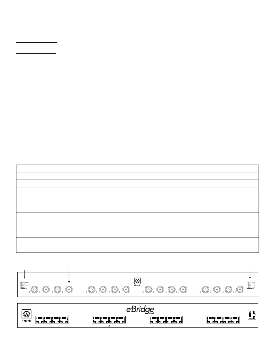
Data In
Data In
Data In
Data In
1
2
3
4
5
6
7
8
9
10
11
12
13
14
15
16
Input 1
Input 2
Structured Cable from
Ethernet Switch/NVR
48VDC/5A,
56VDC/5A
48VDC/5A,
56VDC/5A
10/100
Base-T
1
2
3
4
10/100
Base-T
5
6
7
8
10/100
Base-T
9
10
11
12
10/100
Base-T
13
14
15
16
Ethernet
--
+
--
+
Coax Cable from
eBridge1PCT
or eBridge1PCTX
eBridge16PCRX
(rear)
eBridge16PCRX
(front)
ment in an environment compatible with the maximum ambient temperature (Tma) specified by the manufacturer.
Reduced Air Flow - Installation of the equipment in a rack should be such that the amount of air flow required for safe
operation of the equipment is not compromised. Do not obstruct any air vents on the unit. It is recommended to leave half
space above and below the unit.
Mechanical Loading - Mounting of the equipment in the rack should be such that a hazardous condition is not achieved
due to uneven mechanical loading.
Circuit Overloading - Consideration should be given to the connection of the equipment to supply circuit and the effect
that overloading of the circuits might have on overcurrent protection and supply wiring. Appropriate consideration of
equipment nameplate rating should be used when addressing this concern.
Reliable Earthing - Reliable earthing of rack-mounted equipment should be maintained. Particular attention should be
given to supply connections other than direct connections to the branch circuit (e.g. use of power strips).
1. Attach mounting brackets to eBridge16PCRX unit for rack installation (Fig. 5, pg. 8).
Affix rubber pads to eBridge16PCRX for shelf installation (Fig. 6, pg. 8).
2. Unit should be located in proximity to ethernet switch/network, NVR or video server.
3. Connect UL Listed 48VDC/56VDC (attention to observe polarity) UL Listed power supply to jack marked [Input 1
and Input 2] using two pin plug in connector (supplied) (Fig. 1, pg. 3). Use 22AWG-16AWG wire for this connection.
4. Connect structured cable from ethernet switch/NVR (network video server) to RJ45 jack marked [10/100BaseT]
(Fig. 1, pg. 3).
5. Connect Coax cable to BNC connector marked [Data In] (Fig. 1, pg. 2).
Note: The eBridge is designed to accommodate Megapixel, HD720, HD1080 and VGA (SD) cameras. It is important
to note that some high resolution and high frame rate cameras may demand faster headend processing ability, such as a
PC graphics card to present a quality image. If the headend processing equipment is insufficient in speed, the image may
show pixilation and latency. It is advisable to pretest system if unsure. Alternatively, frame rate and resolution may be
reduced to accommodate system equipment.
Technical Specifications:
Parameter
Description
Connections
BNC for Coax link. RJ45 for ethernet link.
Input power requirements 48VDC/6A, 56VDC/6A per Input (Input 1 and 2) Total current 12A.
Indicators
Blue: Coax Link.
Yellow (RJ45 connector): On - Link, Off - No Link, Blinking - Activity.
Green (RJ45 connector): On - 100Base-TX, Off - 10Base-T.
Green: Power.
Environmental
Conditions
Operating Ambient Temperature: UL60950-1 14ºF to 122ºF (-10ºC to 50ºC).
Relative humidity: 85%, +/ --- 5%
Storage Temperature: --- 4º to 158ºF (--- 20º to 70ºC) Storage
Operating Altitude: --- 1000 to 6,561.679 ft. (--- 304.8 to 2000m).
Regulatory Compliance
UL/CUL Listed for Information Technology Equipment (UL 60950-1). CE approved.
Weights (approx.)
Product: 7.2 lbs. (3.27 kg.), Shipping: 9.2 lbs. (4.17 kg.)
Fig. 1