Fig. 4 - eflow4n configuration, Eflow4n series - 7, Switch detail – Altronix eFlow4NX8D Installation Instructions User Manual
Page 7
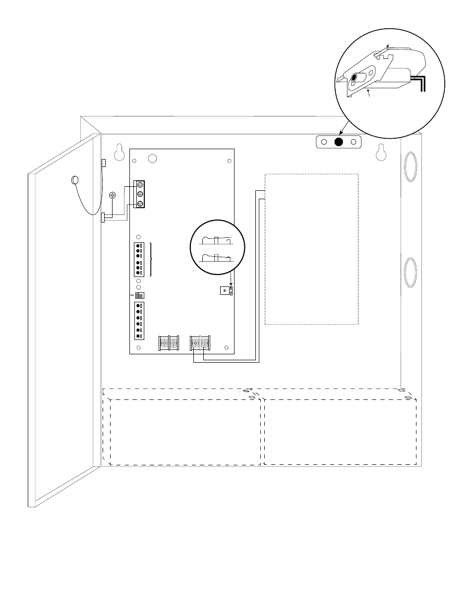
eFlow4N Series
- 7 -
L
G
N
NC
C
NO
NC
C
NO
BA
T F
AIL
AC F
AIL
--- DC +
AC
AC1
DC
--- BAT +
– AUX
+
TRIGGER EO
L
SUPER
VISE
D
5A 250V
RESE
T
GND NO
OPEN --- 24V
CLOSED --- 12V
disable
enable
2 hr
.
1 min
.
AC DELAY
SHUTDOWN
O N
Door
Wire
Strap
(from
Enclosure
to Door)
CAUTION: When power supply board is set for 12VDC use only one (1) 12VDC stand-by battery.
Keep power-limited wiring separate from non power-limited. Use minimum 0.25" spacing.
7AH Rechargeable batteries are the largest batteries that can fit in this enclosure.
A UL Listed external battery enclosure must be used if using 12AH, 40AH or 65AH batteries.
OPEN 24V
CLOSED 12V
Switch Detail
Green
Lead
(ground)
Power-
limited
120VAC
power mains
Non Power-
limited
Battery & AC
Supervision
Circuit
(Power-limited)
Battery
Connections
(Non
Power-limited)
Optional Rechargeable Stand-by
Battery for UL294 Applications.
Note: 12V batteries required for UL603,
UL1481 and Canadian installations.
Optional Rechargeable Stand-by
Battery for UL294 Applications.
Note: 12V batteries required for UL603,
UL1481 and Canadian installations.
PD8UL/PD8ULCB
DC Output to devices
(refer to Fig. 3a or 3b
for board configuration pg. 6)
Edge of
Enclosure
to Access Control
Panel or
U.L. Listed
Reporting
Device
Enclosure
Sentrol
model # 3012
Tamper Switch
or equivalent
(Not Included)
Fig. 4 - eFlow4N configuration