2 adjustment – VEGA VEGAMIP R62 Receiving unit - Transistor User Manual
Page 30
With the mode switch (min./max.) you can change the switching status
of the transistor output. You can set the required mode according to
the "Function chart" (max. - max. detection or overflow protection, min.
- min. detection or dry run protection).
With these keys (7 and 8) you can adjust the switching point to the
medium.
Depending on the process, the sensitivity of VEGAMIP 62 must be set
higher or lower.
Pressing the "<--" key makes the sensor more sensitive. Pressing the
"
-->" key makes the sensor less sensitive.
You can also adjust the switching delay with the two keys.
By means of the LED indicating strip, you can see the actual receive
level during adjustment.
When the indication moves to the right, the instrument is less sensitive,
to the left more sensitive.
6
.2 Adjustment
The microwave barrier can only be adjusted when it is uncovered.
Make sure that no measured medium or vessel installations are
between the emitting and receiving unit.
Select the requested mode (min./max.) according to the function chart.
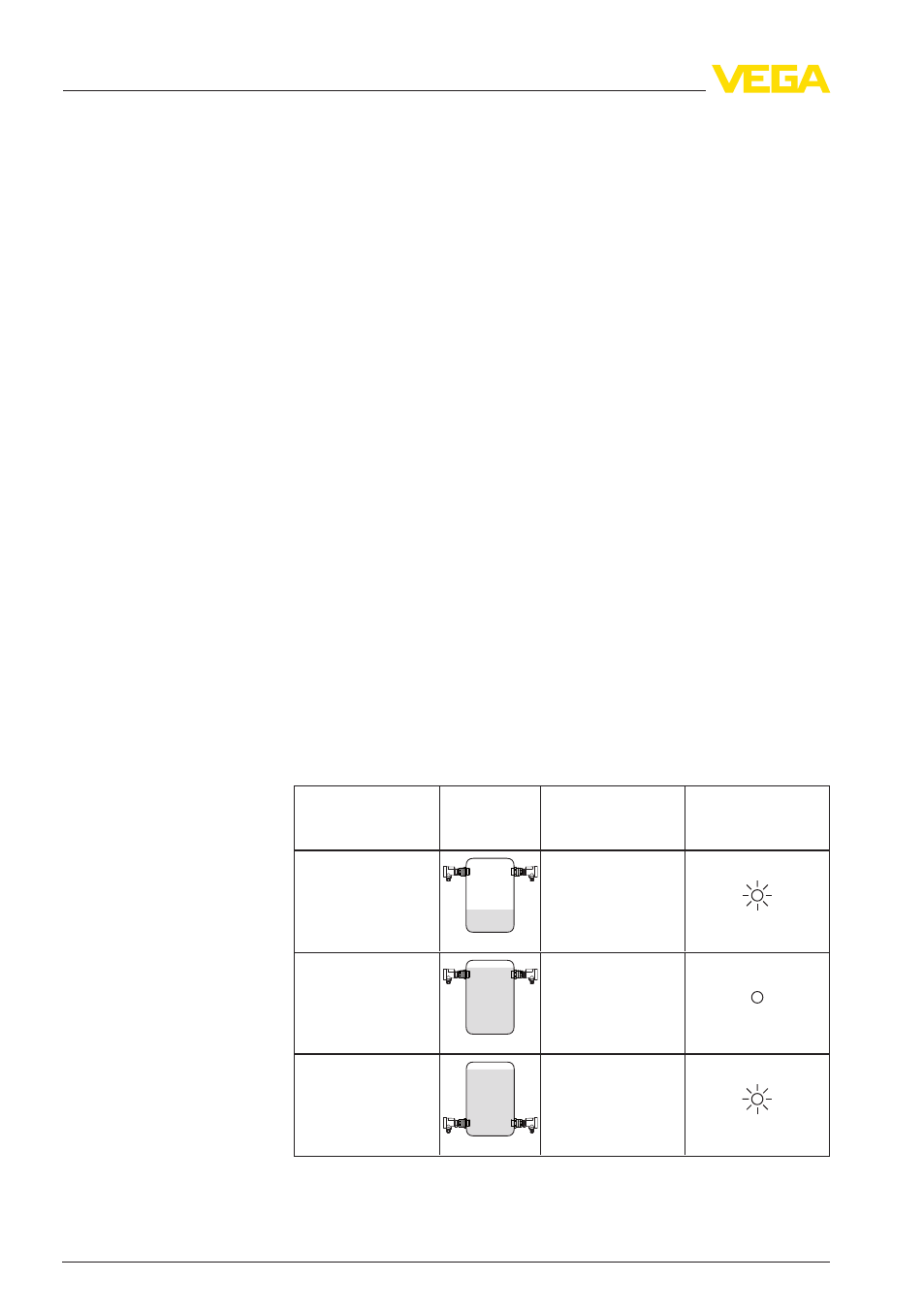
The following function chart provides an overview of the switching
statuses depending on the set mode and level.
Level
Switching status
Signal lamp -
Switching output
(yellow)
Mode max.
Overflow protection
closed
Mode max.
Overflow protection
open
Mode min.
Dry run protection
closed
Mode switch (1)
Sensitivity adjustment
(7, 8)
LED indication strip -
receive level (9)
Prerequisites
Mode
30
VEGAMIP R
62 • - Transistor
6 Setup
41911
-EN
-120228