VEGA VEGAMET 391 4 … 20 mA_HART User Manual
Page 44
44
8 Application examples
VEGAMET 391 • 4 … 20 mA/HART
36032-EN-130701
again. If the level continues to rise despite operation of a pump, an
additional pump switched on when the level exceeds the 75 % switch-
ing point. And if the level still rises further due to extreme inflow and
exceeds the 90 % limit, pump 3 is also switched on.
Select in the DTM navigation section the menu items "Meas. loop -
Outputs - Relay".
•
Set mode "Pump control 4" for relays 1 … 3.
•
Enter the switching points for the affected relays as follows:
– Relay 1 upper switching point = 60.0 %
– Relay 1 lower switching point = 10.0 %
– Relay 2 upper switching point = 75.0 %
– Relay 2 lower switching point = 10.0 %
– Relay 3 upper switching point = 90.0 %
– Relay 3 lower switching point = 10.0 %
The function of pump control 4 is shown in detail in the following dia-
gram. The previously described example is used as a basis.
Rel. 1: 60% On
Rel. 1..3: 10% Off
Rel. 2: 75% On
Rel. 3: 90% On
t(h)
Rel. 3
Rel. no.
Rel. 2
1 2
3
1
2
3
1
2
3 1 2
Rel. 1
Fig. 16: Example of pump control 4
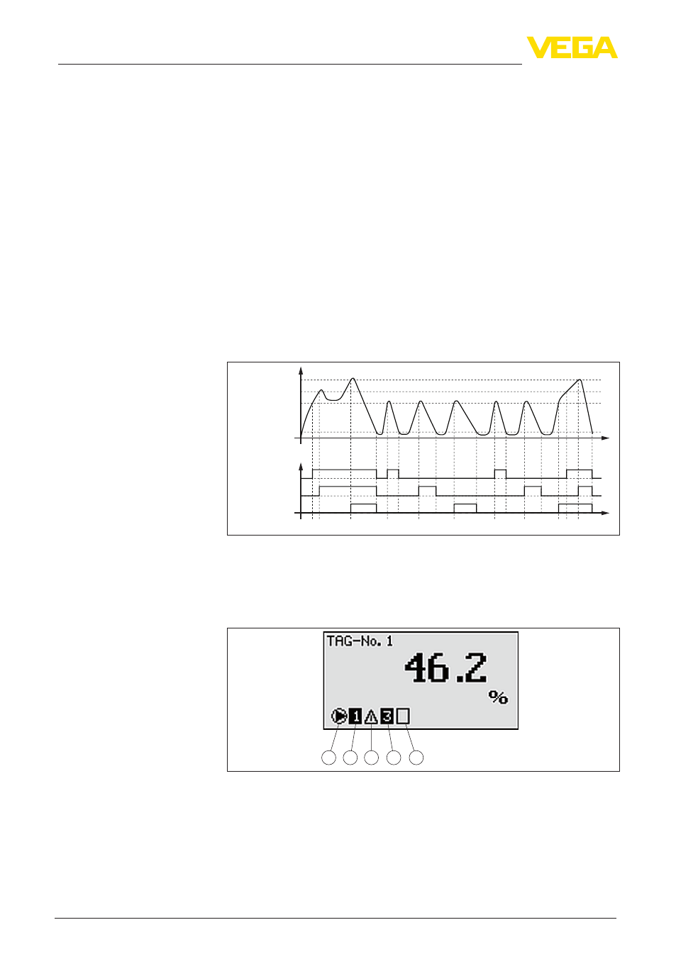
When pump control is activated, the assigned relays and possible
pump malfunctions are also displayed in the measured value indica-
tion.
1 2 3 4 5
Fig. 17: Display indication of a pump control
1 Symbol activated pump control
2 Relay 1 is assigned to the pump control
3 Relay 2 is assigned to the pump control and signals failure
4 Relay 3 is assigned to the pump control
5 Relay 4 is free or not assigned to the pump control
Setup
Display indication