Vutec LECTRIC IV - Installation Instructions User Manual
Page 8
7
04/21/08 Rev D
LIIe-INST_D
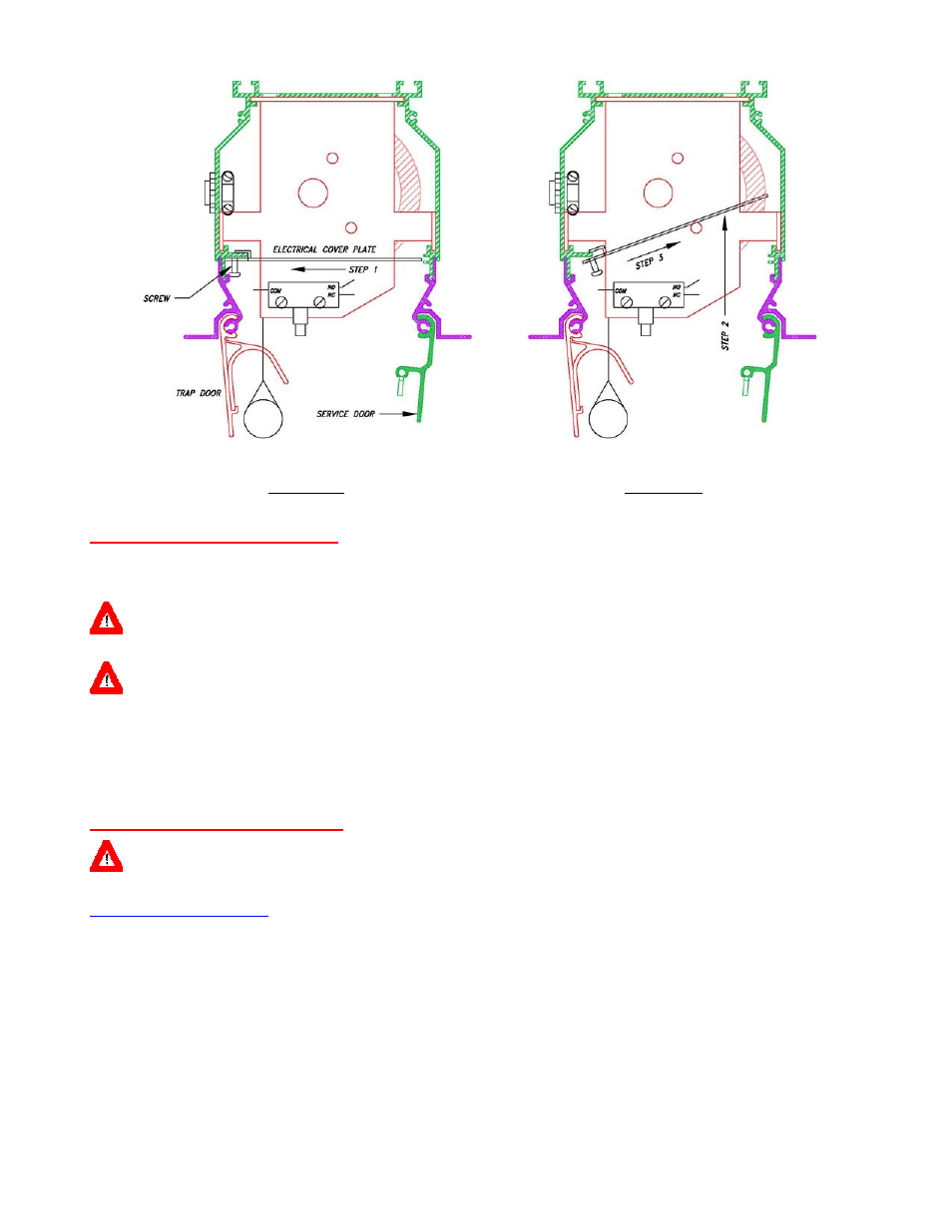
Figure 5a Figure
5b
UPPER LIMIT ADJUSTMENT
The upper lim it for the screen is when the trap door closes to trip the DCL switch to shut off the m otor. The
DCL switch may be moved up or down to adjust the closeness of the trap door. Make adjustments as necessary.
CAUTION: BE SURE THE MOTOR IS SHUT OFF WHEN THE TRAP DOOR IS CLOSED. IF THE MOTOR STILL RUNNING (HUMMING) THEN
THE DCL SWITCH MUST BE ADJUSTED TO SHUT OFF THE MOTOR.
WARNING: FAILURE TO CHECK AND CORRE CT THE M OTOR SHUT O FF C ONDITION AF TER THE TRAP DOOR IS CLOSED MAY
CAUSE SEVERE DAMAGE TO THE MOTOR AND VOID THE WARRANTY.
The second upper limit for the screen is set by the motor limit switch (Yellow button or Yellow hex socket).
If the screen missed the hooks of the trap door; it should co me up close the screen roller and stop. It should not
be allowed to jam between the housing and the roller.
LOWER LIMIT ADJUSTMENT
WARNING: UNLESS OTHERWISE SPECIFIED AND ORDERED, STANDARD LEADER DROP IS 12 INCHES MAXIMUM. EXCEEDING THE
MAXIMUM MAY CAUSE THE SCREEN TO FALL OFF THE ROLLER AND VOID THE WARRANTY.
PUSH BUTTON LIMIT SWITCH
Key features of the push button limit switch:
⇒
The limit switch is a spring-loaded button. It works exactly like a push on/off pen.
⇒
Button pushed in - motor limit switch disengaged, free running, screen m ust be stopped by control
switch.
⇒
Button pushed out - m otor limit switch is engaged to stop the screen at the point at which the screen
was stopped and the limit switch pushed out.