Vutec LECTRIC IV - Installation Instructions User Manual
Page 10
9
04/21/08 Rev D
LIIe-INST_D
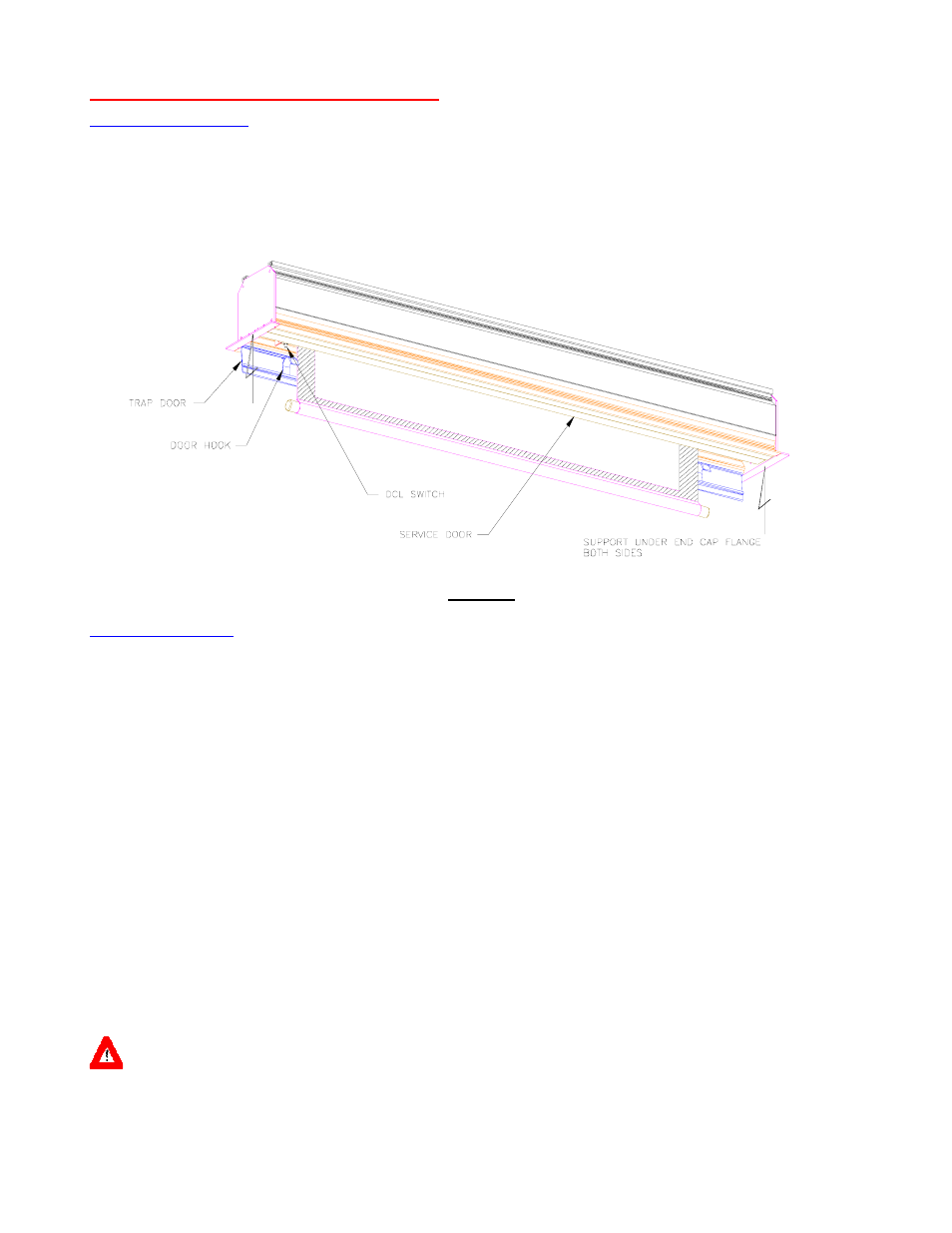
SCREEN ROLLER ASSEMBLY REMOVAL
PRIOR TO INSTALLATION
Support the unit from under end cap flanges (Figure 7) and clear of trap door travel.
Referring to Figure 4, connect the switch to operate the screen.
Send the screen down just enough for the trap door to open. Proceed to next section.
Figure 7
INSTALLED IN CEILING
Send the screen down just enough for the trap door to open.
At each end of the service door; slide the latch pin (Figure 2b) toward the center to open the door.
Send the screen back up without allowing the screen to catch the door hooks. Stop the screen (Figure 8) just
above the door hooks.
Turn off power to the screen.
Referring to Figures 5a and 5b, open the electrical cover plate, and pull down the wire nuts bundle.
Disconnect wires from all wire nuts. Use a 5/16” hex key to disconnect m otor ground form top ground screw
shown and field chassis ground shown in Fig. 4.
Using 1/8 (3mm) hex key to loosen the set screws of the Idler bracket.
Support the full length of the screen roller assembly (Figure 9) while moving the Idler bracket to the right. Move
the Idler bracket off the shaft of the roller.
Move the screen roller assembly including the m otor to th e right just enough to clear the m otor head from the
head bracket (Figure 9). Lower the screen roller assembly out of the housing.
Reinstalling the screen roller assem bly with the m otor included is the reverse of the rem oval. Be sure the lim it
switches facing down as shown in Figure 2a. Re-wire following Fig 4..
CAUTION: REINSTALL OF THE SCREEN ROLLER ASSEMBLY MAY REQUIRE LOWER LIMIT ADJUSTMENTS.