Velleman К8077 User Manual
Page 22
22
Make sure that the IC’s are removed from their sockets.
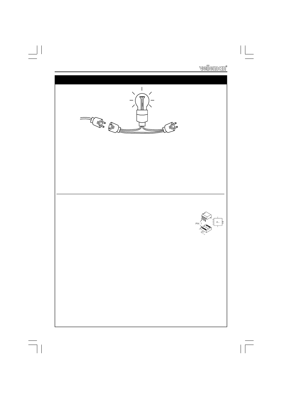
We recommend to construct a small test-jig, and connect the unit as shown below.
1. Put the power switch in the ‘I’ position
2. Put the ‘MODE’-switch in the ‘AUTO-ON’-position.
3. When power is applied, the ‘POWER’ led should light.
If the light bulb remains lit, turn off the power immediately and check your circuit.
By means of a multi meter set to DC volts, you can check the following voltages:
Use the GND tab next to the red transformer wire as ‘-‘
•
J2: +15V
•
J3: -15V
•
Left lead of R33: +24V or slightly higher
•
Right lead of R37: +5V
4. Turn off the power and mount the IC’s.
5. Turn on the power again repeat the above
measurements.
If OK, flip the ‘MODE’-switch to ‘ON’
Once again, if the light bulb remains lit, turn off the power immediately and
check your circuit. LD3 should light.
Check the following voltages:
•
Cathode D11: +35V
•
Anode D12: -35V
6. Connect the multimeter across R60 (right power resistor).
7. Meter should read 0V (Mind the polarity) !
8. Adjust RV3 until the meter reads 10mV
Wait a while until the readout remains constant
9. Remove the multimeter and turn off the power
30. Testing the unit
60W
(120 / 235VAC)
Power supply
120 / 235VAC
From K8077
Testing the unit
IC1 : TL072
IC2 : TL074
IC3 : VK8077
(programmed PIC10F200-I/PG)