Experiment 8: waveform with adjustable frequency – Velleman projects EDU06 Assembly instructions User Manual
Page 18
18
Experiment 8: Waveform with adjustable
frequency
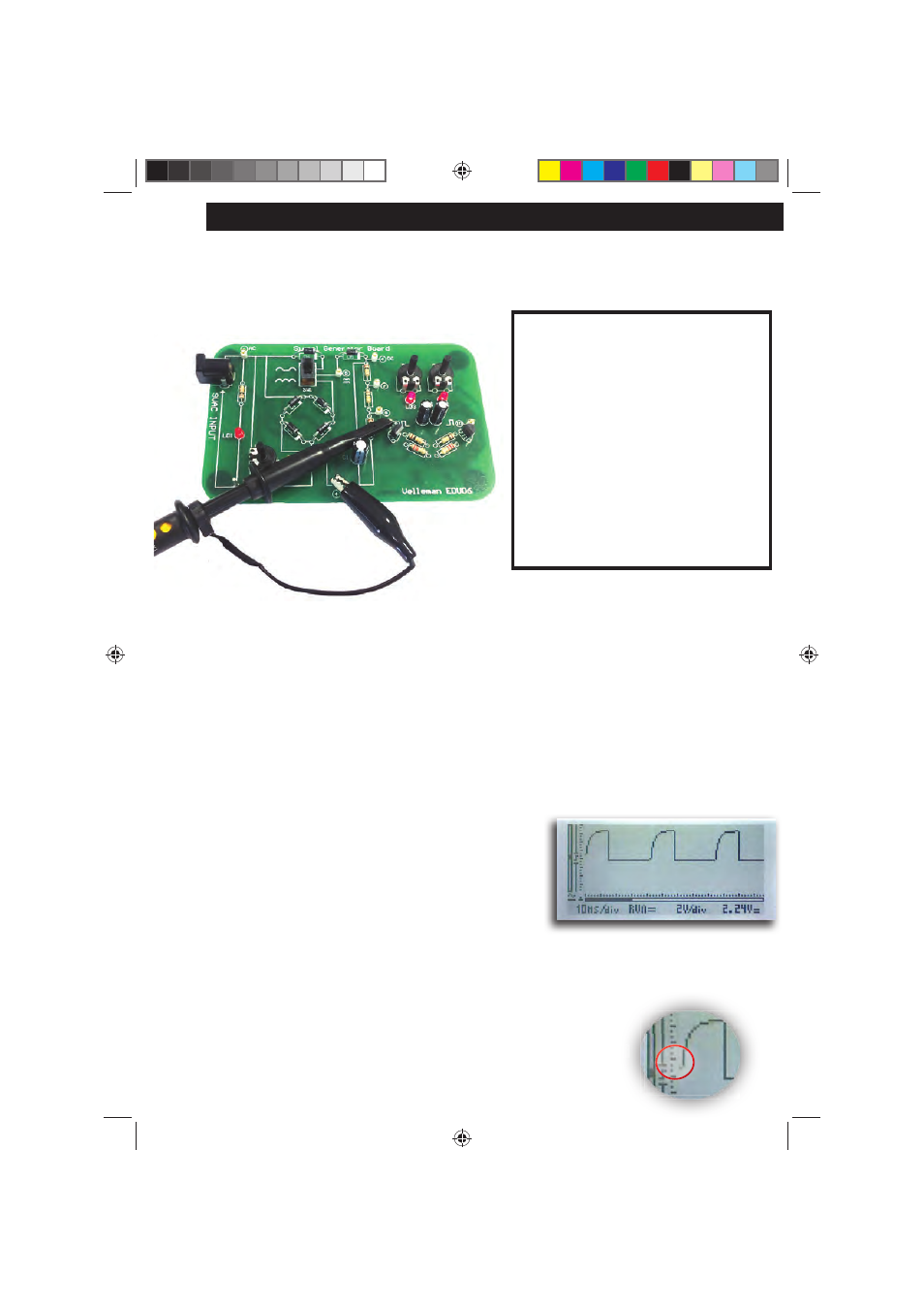
Connection layout:
Connection summary:
GND clip : 4
Probe tip : 9
Purpose:
The purpose of this experiment is to demonstrate the use of the ‘trigger’-function.
How?:
Place the probe switch “x1/x10” to ‘x1’.
1.
Flip SW1 into the ‘full wave’-position.
2.
Turn on the HPS140 Handheld Pocket Scope, it will turn on in ‘auto-setup’ mode.
3.
Select DC coupling.
Set unit to 10ms/div and 2V/div. Adjust RV2 and RV3 in such
a way that the waveform looks like the the screenshot below.
The unit displays a square wave. The rising edge of the square
wave is not perfectly ‘square’, due to the limitations of this simple
two-transistor circuit. Anyway, the resulting waveform is fi ne for
our experiment.
As you can see, the displayed waveform is perfectly stable, it does not jump from left to right.
The circuit responsible for this is the triggering circuit.
How does it work?
Take a close look at the left hand side of the screen, where the waveform
starts. You will see a vertical line with a small ‘gap’. In this gap, a ‘slope’-
symbol is displayed. This ‘gap’ determines the trigger point, the place where
the scope will ‘trigger’ or will start drawing the waveform on the screen.
NOTES:
Waveform with adjustable frequency
y
y
re