MSD 8481 LT-1 Distributor Cap & Rotor Kit, '93-'94 GM, LT-1, 350_5.7L SFI Installation User Manual
Page 3
INSTALLATION INSTRUCTIONS
3
M S D
• W W W . M S D P E R F O R M A N C E . C O M • ( 9 1 5 ) 8 5 7 - 5 2 0 0 • F A X ( 9 1 5 ) 8 5 7 - 3 3 4 4
VACUUM LINE ROUTING
This kit is supplied with a vacuum
line kit that will aid in venting the
distributor cap. One hose assembly
connects to a vacuum port on the
intake manifold while the other line
connects to the air inlet going into
the throttle body. In order to take
advantage of this venting technique,
you will need to seal the three small
holes on the bottom of the distributor
(Figure 2).
1. Connect the long hose assembly
to the lower vacuum inlet of the
MSD distributor cap (Figure 7).
Use the supplied clamp to secure
the hose.
2. Route the vacuum line around the
side of the engine and up to the
intake manifold. Splice into the
hose that connects just over the
PCV valve (Figure 8). Also note the check valve that is
in-line. The black side of the valve must face towards the
vacuum source.
3. Connect the smaller vacuum line to the fresh air inlet port
of the isolator (see Figure 4).
4. Locate the supplied 90° vacuum nipple. Using a 3/16" drill
bit, drill a hole in the air intake duct and install the nipple
(Figure 9). Make sure the barb goes through and into the
duct. Connect the line from the distributor cap to this inlet.
This line completes the fresh air circulation through the
distributor cap (Figure 11).
5. Install the spark plug wires ensuring they are routed to the
correct terminal (Figure 10).
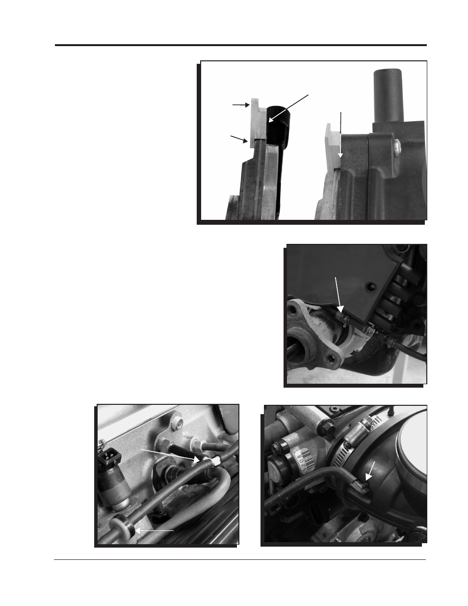
NOTE
DIFFERENT
THICKNESSES
EDGE MUST
SIT FLUSH
WITH
HOUSING
Figure 6 Installing the Clamp-Block.
Figure 7 Install the Lower Vacuum Line.
Figure 8 Connecting the Vacuum Source.
LOWER VACUUM
INLET
VACUUM
SOURCE
CHECK
VALVE
Figure 9 Installing the Fresh Air Line.
FRESH AIR
SOURCE