MSD 8481 LT-1 Distributor Cap & Rotor Kit, '93-'94 GM, LT-1, 350_5.7L SFI Installation User Manual
Page 2
2
INSTALLATION INSTRUCTIONS
M S D
• W W W . M S D P E R F O R M A N C E . C O M • ( 9 1 5 ) 8 5 7 - 5 2 0 0 • F A X ( 9 1 5 ) 8 5 7 - 3 3 4 4
INSTALLATION
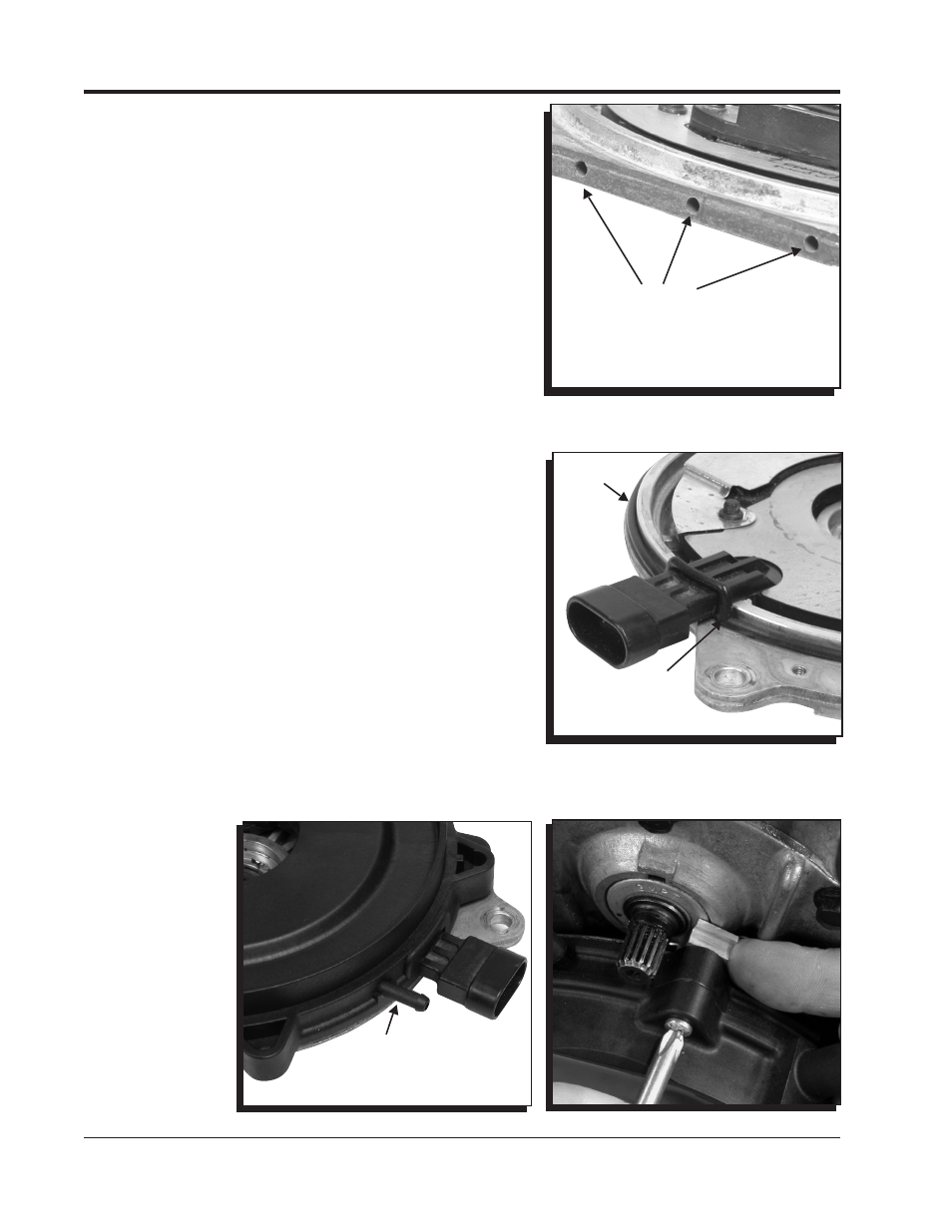
Before proceeding, you will need to seal the distributor
housing's original vent holes. These are located at the bottom
of the distributor housing (Figure 2). Use a silicone gasket
sealer or equivalent.
1. Locate and install the distributor-to-isolator seal then
position the isolator in place on the distributor (Figure
3). Note the fresh air inlet port on the isolator (Figure 4).
2. Make sure the optical disk and shims are installed in the
right position, then install the new rotor with the supplied
hardware. The rotor only installs one way. Make sure it
sits squarely on the shaft.
Note: It is recommended to use a threadlocker like Loctite
Blue on the two rotor screws.
3. Make sure that the Isolator-to-Cap seal is installed on the
Isolator, then install the cap using the supplied Phillips
head screws.
4. Locate four metric Phillips screws that retain the cap
assembly. There is also a standard, slightly larger and
longer Phillips screw. This screw is used with the Clamp-
Block that goes in the cap tab located between the wiring
harness and the coil wire tower (Figure 5).
5. Note that the Clamp-Block has two different thicknesses
(Figure 6). Some distributor housings have a machined
surface while others are cast. Determine which side works
best in your application to secure the top mount of the
cap. Once the direction is achieved, slide the Clamp-Block
into position and screw the standard Phillips screw into
position (Figure 6).
6. Connect the distributor connector followed by the coil
wire and spark plug wires. Ensure that each wire is in the
correct location (Figure 10).
7. Install Vacuum hoses as shown on page 3 (Figures 7 - 9).
8. The distributor is assembled. Reinstall all of the compo-
nents in the reverse order. It is recommended to follow
along with your
vehicle’s ser-
vice manual.
Figure 4 Isolator Inlet.
Figure 5 Clamp-Block Mounting Boss.
Figure 3 Installing the
Distributor-to-Isolator Seal.
SEAL THREE HOLES
WITH SILICONE
SEALER OR
EQUIVALENT.
Figure 2 Sealing the Vent Holes.
ADD SILICONE
SEALER BENEATH
CONNECTOR
FRESH AIR INLET
SEAL