MSD 7530T Programmable Digital-7 Ignition Control Installation User Manual
Page 2
2
INSTALLATION INSTRUCTIONS
M S D
• W W W . M S D P E R F O R M A N C E . C O M • ( 9 1 5 ) 8 5 7 - 5 2 0 0 • F A X ( 9 1 5 ) 8 5 7 - 3 3 4 4
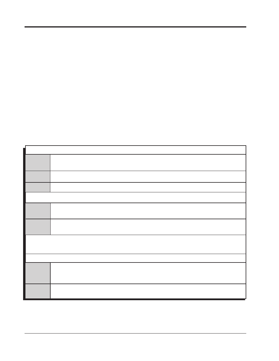
WIRING
Ignition supply wire. Connects to battery positive (+) terminal or battery junction.
Note: Do not connect to the alternator.
Ignition supply Ground wire. Connect to battery negative (-) terminal or engine block.
Red
On/Off switch wiring. Connects to a switched 12 volt source.
Primary Coil Leads
Orange
Connects to the coil positive (+) terminal. This is the only wire that makes contact to
the coil positive terminal.
Black
Connects to the coil negative (-) terminal. This is the only wire that makes contact to
the coil negative terminal.
WARNING: High voltage is present at the coil primary terminals. Do not touch the coil or connect
test equipment to the terminals while the engine is running or cranking.
Trigger Wires
Violet/
Magnetic pickup, 2-pin connector. Plugs into an MSD Distributor or Crank Trigger
pickup. Violet is positive, Green is negative.
Note: When this connector is used, the
White wire is not connected.
White
Trigger input for electronic ignition amplifiers, an ECU’s trigger or points.
Note: When this wire is used, the magnetic pickup wire is not connected.
Green
2-Pin
Heavy
Red
Heavy
Black
PROTECTION
The MSD Digital-7 Programmable has a built in reverse polarity protection circuit. This will protect the ignition
in the event of wrong connections. It will also shut off for protection from a surge in power. The ignition will still
operate once the surge or polarity is corrected.
LED INDICATOR
There is an LED that monitors the status of the Ignition. The LED will verify trigger inputs and will flash trouble
codes such as a Code 2 for No Cam Sync, Code 3 for Low Battery supply voltage or Code 4 for Traction Control
Detection.
CAMSHAFT SYNCHRONIZATION
This is used only in applications where the individual cylinder timing is going to be used. The 2-pin connector
with a Light Blue and Light Green wire connects to a sensor that is used to synchronize or alert the Ignition as to
when the number one cylinder is going to be triggered. With this information, the Ignition knows which cylinder
is being fired allowing for the individual cylinder timing capabilities. A Universal Cam Sensor is available from
MSD as PN 2346. MSD offers two kits to use for sync signals: Universal Cam Sensor, PN 2346 and Fiber Optic
Inductive Pickup Kit, PN 7555.